

Bespoke Spring Design Leg Angles: A How-To Guide
Table of Contents
- Understanding Torsion Spring Basics and Leg Angle Fundamentals
- What You'll Need Before Specifying Your Custom Spring
- Measuring and Communicating Torsion Spring Free Angle
- Defining Torsion Spring Leg Position and Orientation
- Selecting the Right Torsion Spring End Types for Your Design
- How to Specify a Custom Torsion Spring: Step-by-Step Workflow
- Common Specification Mistakes to Avoid
- Tolerance, Inspection, and Angle Verification After Manufacturing
- Frequently Asked Questions
Last Updated: October 12, 2026
Understanding Torsion Spring Basics and Leg Angle Fundamentals
A torsion spring is a coiled metal wire that stores and releases rotational energy when twisted. Unlike compression springs that resist pushing forces, torsion springs resist turning forces and return an assembly to its original position after rotation.
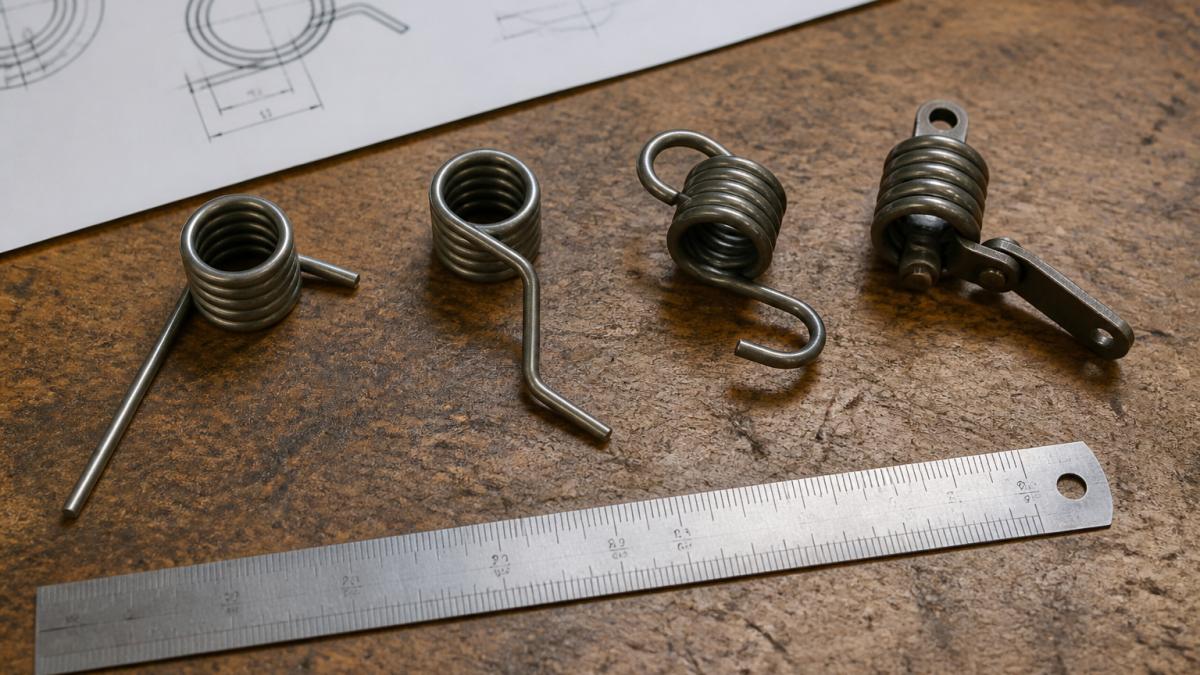
The core of any torsion spring consists of three elements: the coil body (the wound wire itself), the wire diameter (which determines strength), and the legs (the straight or bent extensions that attach to your assembly). The legs are load-bearing components that directly affect how much torque your spring delivers and how reliably it performs.
How the coil body, wire diameter, and leg geometry work together
The coil body stores the rotational energy. When you twist the spring, the wire inside that coil flexes. A tighter coil (smaller diameter) is more compact; thicker wire makes the spring stronger overall.
But leg geometry is critical: the legs determine where and how force gets applied. A leg that's too short won't reach your mounting point; a leg at the wrong angle creates uneven stress distribution and premature failure.
What You'll Need Before Specifying Your Custom Spring
Before you contact a spring manufacturer, gather three pieces of information about your assembly.
First, the physical layout. How much space do you have? Where do the legs need to contact? What direction does your assembly rotate?
Second, the torque requirement. How much rotational force does your mechanism need at specific angles? Does it hold position or assist movement?
Third, any constraints: temperature extremes, corrosive environment, tight tolerances, frequency of use. Each narrows the material and design options.
Many teams skip this step and send vague requests, leading to multiple revisions and delays.
Measuring and Communicating Torsion Spring Free Angle
Free angle is the angular position of the legs when the spring sits unloaded, no torque applied, no assembly attached. It's the baseline measurement that defines everything else about your spring's geometry.
Visual method for documenting free angle on your assembly drawing
The clearest way to specify free angle is a technical drawing. Show the coil body from above (a circle), draw one leg pointing straight up (12 o'clock), then draw the other leg at the angle you need.
Include a note: "Free angle measured in the plane perpendicular to the coil axis." This eliminates confusion about the measuring plane, critical when legs are offset in three dimensions.
A visual drawing beats a written description every time. The manufacturer can see exactly what you need instead of interpreting ambiguous language.
Distinguishing free angle from working angle in your specification
Working angle is where the legs sit when your assembly is in its normal operating position. If your free angle is 90° but your mechanism rotates the spring to 45° during operation, then 45° is your working angle.
This distinction tells the manufacturer how much deflection the spring experiences in real use. A spring at 90° free angle working at 45° is twisted 45° from rest, deflection that affects stress, fatigue life, and long-term reliability.
Document both on your drawing:
- Free Angle: 90° (unloaded)
- Working Angle: 45° (during operation)
- Angular Deflection: 45° (the difference)
The manufacturer uses this to predict how long your spring will last and whether the material can handle the repeated twisting.
Defining Torsion Spring Leg Position and Orientation
Leg position determines where your spring contacts the assembly. Leg orientation determines the direction of rotational force.
Leg length, mounting point contact, and assembly clearance
Measure from the edge of the coil body to where each leg touches your assembly, that's leg length.
Clearance matters too: legs too long interfere with adjacent components, too short won't reach. Either way, the spring won't work.
A common mistake is assuming "close enough" is acceptable.
Specify leg length to the nearest millimetre. Include a tolerance, for example, "Leg Length: 25 ± 1 mm." This tells the manufacturer how precisely they need to form the legs.
Angular relationships between legs and coil body
The angle between each leg and the coil body affects how torque flows into your mechanism. Legs pointing the same direction (0° apart) make the spring act like a simple hinge; opposite directions (180° apart) let it push or pull depending on rotation direction.
Document this on your drawing with clear angular measurements. Show the coil from the end view. Mark the angle of each leg relative to a reference line (often the 12 o'clock position).
Include this note: "All angles measured in the plane perpendicular to the coil axis, with reference to the coil's centre line."
Selecting the Right Torsion Spring End Types for Your Design
The legs don't all look the same. Different end types serve different purposes, and choosing the right one affects how reliably your spring works.
Straight legs, offset legs, hooked ends, and hinged configurations
Straight legs extend directly from the coil body at your specified angle.
Offset legs bend away from the coil body plane before reaching their final angle, creating clearance between leg and coil when your assembly is tight.
Hooked ends curl back on themselves into a loop at the leg tip, gripping shafts, pins, or edges securely and preventing the spring from sliding off during assembly or vibration.
Hinged ends (also called "eyes" or "loops") form a complete circle at the leg tip.
How end type affects torque delivery, contact point, and fatigue life
Each end type changes how force concentrates at the contact point. Straight legs concentrate stress at the contact surface; hooked ends spread it over a curved surface, reducing peak stress; hinged ends distribute it across the pin contact area.
Lower peak stress means longer fatigue life. For applications requiring millions of cycles, end type directly impacts how long the spring survives.
Contact point geometry also affects torque delivery consistency: a hook gripping a shaft delivers torque smoothly across the full rotation, while a straight leg on a flat surface can slip or bind if tolerances are loose.
How to Specify a Custom Torsion Spring: Step-by-Step Workflow
Specifying bespoke spring design leg angles requires translating your assembly layout into precise spring geometry. Follow this workflow to get it right the first time.
Step 1: Translate your assembly layout into spring geometry
Start with your assembly drawing. Identify where the spring sits. Mark where each leg must contact. Measure the space available, coil diameter, leg length, clearance from other parts.
Sketch the spring unloaded (free angle) and again in its working position, the difference is your deflection range.
Create a simple technical drawing showing:
- Coil body (circle, viewed from the end)
- Both legs with their angles marked
- Dimensions: coil diameter, wire diameter, leg lengths
- Reference notes: "Free angle measured in plane perpendicular to coil axis"
This drawing becomes your specification foundation.
Step 2: Define torque requirements and angular deflection
Determine how much rotational force your spring must deliver and at what angle it reaches maximum load. Does it hold position, assist movement, or return the assembly to rest?
Specify torque at a known angle. For example: "Torque required: 2.5 Newton-metres at 45° deflection from free angle."
Include the full deflection range: "Minimum deflection: 0°. Maximum deflection: 90°."
This tells the manufacturer the stress envelope your spring will experience. They use it to select wire diameter and material.
Step 3: Communicate leg angles, material, and tolerance on your drawing
Create a final technical drawing with every specification, in clear, unambiguous language.
Document:
- Free angle (degrees)
- Leg lengths (millimetres, with tolerance)
- Leg angles relative to coil axis (degrees)
- End type (straight, offset, hooked, hinged)
- Wire diameter (millimetres)
- Coil diameter (millimetres)
- Material (spring steel, stainless steel, other)
- Torque requirement at a specified angle (Newton-metres)
- Angular deflection range (degrees)
- Surface finish or coating (if needed)
Include a note: "All angles measured in the plane perpendicular to the coil axis."
Send this drawing with your request for quotation. A quality manufacturer will review it, confirm feasibility, and respond within 12 hours with questions or a quote. At SpringXpert, we guarantee that timeframe because clear specifications make the process faster.
Common Specification Mistakes to Avoid
Underspecifying free angle and tolerance
Many teams specify free angle without a tolerance, writing "Free Angle: 90°" and assuming the manufacturer hits it exactly. In reality, coils form within a tolerance band, usually ±2-3°.
If your assembly requires a precise free angle, specify it: "Free Angle: 90° ± 1°." This tells the manufacturer how tight the tolerance must be. Tighter tolerances cost more but ensure consistent fit.
Omitting tolerance leads to springs that don't fit: the leg angle is off by a few degrees and your mechanism binds or won't hold position.
Ignoring wind direction and coil handedness effects
Wind direction is which way the coil spirals, clockwise or counterclockwise viewed from one end. It affects how the legs exit the coil and which direction the spring naturally twists.
If your assembly requires the spring to twist in a specific direction, specify it: "Wind direction: right-hand" or "Wind direction: left-hand."
Ignoring wind direction can produce a spring that twists the wrong way: the torque curve works against your mechanism instead of with it, fighting your assembly rather than assisting it.
Confusing leg angle with torque or spring rate
Leg angle is geometry, the physical position of the legs. Torque is the rotational force the spring delivers. Spring rate is how much the torque changes per degree of deflection.
These are independent: a spring with legs at 90° can have high or low torque depending on wire and coil diameter, and a steep leg angle doesn't automatically mean high torque.
Specify each separately:
- Leg angle: 90° (geometry)
- Torque at 45° deflection: 2.5 Newton-metres (force requirement)
- Spring rate: 0.05 Newton-metres per degree (stiffness)
Confusing these leads to incorrect specifications and wasted iterations.
Tolerance, Inspection, and Angle Verification After Manufacturing
Once your custom spring arrives, verify it matches your specification before assembly.
Measure free angle with a protractor or angle gauge.
Measure leg lengths with callipers; each should match the specified length within tolerance.
Check for surface defects, cracks, rust, or deformation.
Verify the spring deflects smoothly through its working range.
If anything is out of specification, contact the manufacturer immediately.
At SpringXpert, every custom spring undergoes inspection before shipment. We verify dimensions, angles, and material properties.
Specifying bespoke spring design leg angles correctly means fewer revisions, faster assembly, and longer spring life.
Frequently Asked Questions
What is the free angle of a torsion spring?
The free angle is the angular position of a torsion spring's legs when the spring is unloaded and not deflected. It defines the starting point for your assembly and determines how much rotational travel is available before the spring reaches its working angle. Specifying free angle accurately ensures your mechanism operates within the intended torque range and prevents premature fatigue or binding.
How do you measure and communicate torsion spring leg angles on a drawing?
Measure the angle between each leg and a reference axis (typically the coil body or a datum line) using a protractor or angle gauge. On your drawing, show the free angle in degrees, indicate whether legs are offset or angled relative to the coil, and specify the contact points where the legs engage your assembly. Include a top and side view to eliminate ambiguity about three-dimensional orientation.
How does torsion spring leg position affect an assembly?
Leg position determines where the spring makes contact with your mechanism, how torque is transmitted, and how much angular deflection occurs before interference. Incorrect leg length or angular orientation can cause binding, uneven load distribution, premature wear, or failure to deliver the required torque at your working angle. Precise leg positioning ensures smooth operation and predictable performance across your design life.
What is the difference between free angle and working angle in a torsion spring specification?
Free angle is the unloaded leg position; working angle is the leg position after the spring has been deflected by your assembly. The difference between them is angular deflection, which determines how much torque the spring delivers. Confusing these two is a common specification error that leads to springs that either under-perform or fail prematurely under load.