

Understanding Spring Terminology: The Engineer’s Essential Reference Guide
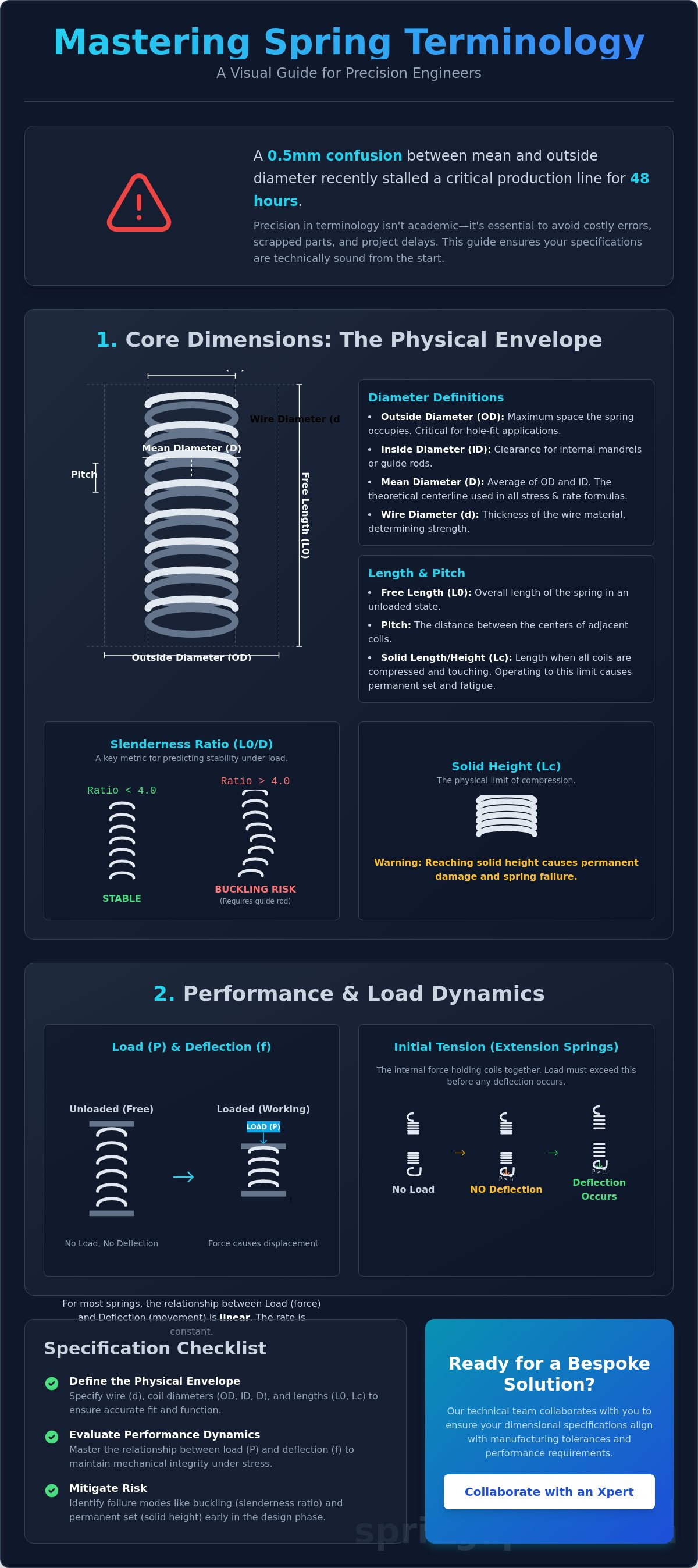
Last Tuesday, Mark, a senior design engineer at a precision plant in Sheffield, realized that a 0.5mm confusion between mean diameter and outside diameter stalled a critical production line for 48 hours. This type of technical miscommunication is common when engineers and suppliers aren't aligned on specific definitions. Most professionals agree that precision in the design phase is the only way to avoid the high costs of scrapped parts and delayed assemblies. Engineers who focus on understanding spring terminology avoid these pitfalls by ensuring their specifications are technically sound from the start.
We've developed this guide to help you master the specialized lexicon required to specify, design, and procure industrial springs for any application. You'll gain the confidence to write technical specifications that leave no room for error, whether you're dealing with complex alloys or strict tolerances. This reference categorizes essential terms by their practical application, providing you with a systematic framework for your next bespoke engineering project and future collaboration with our technical team.
Key Takeaways
- Define the physical envelope by understanding spring terminology for wire and coil diameters, ensuring accurate integration into British engineering projects.
- Evaluate performance dynamics by mastering the relationship between load and deflection to maintain mechanical integrity under operational stress.
- Distinguish between active and inactive coils and select end configurations that optimize force distribution for your specific industrial application.
- Mitigate risk by identifying common failure modes like fatigue and creep through a deeper understanding of tensile strength and elastic limits.
- Streamline the procurement of bespoke solutions by applying precise tolerances and technical standards to your manufacturing specifications.
Core Dimensional Terminology: Defining the Physical Envelope
Precision engineering requires a shared vocabulary to translate a schematic into a functional component. Physical dimensions serve as the primary constraints for any spring specification. When a British engineer at a Midlands manufacturing facility reviews a blueprint, the first checks involve the spatial limits of the application. Misinterpreting these values leads to interference or mechanical failure. Mastering the basics is the first step in understanding spring terminology for industrial applications.
The slenderness ratio, calculated by dividing the free length by the mean diameter, dictates the stability of a compression Spring (device) during operation. If this ratio exceeds 4.0, the component will likely buckle under load. This physical reality necessitates the use of a guide rod or sleeve to maintain axial alignment. Engineers must also distinguish between wire diameter (d) and coil diameter. While the wire diameter determines the material's cross-sectional strength, the coil diameter defines the leverage and flexibility of the final part.
Diameter Definitions: OD, ID, and Mean
Outside Diameter (OD) defines the maximum space the spring occupies. It's critical for hole-fit applications where a 0.5mm clearance might be the difference between smooth operation and binding. Inside Diameter (ID) specifies the clearance for internal mandrels or rods. The Mean Coil Diameter (D) is the mathematical average of the OD and ID. This value is used in nearly all engineering formulas to calculate stress and rate. It's the theoretical centerline of the wire coil.
Length and Pitch Characteristics
Free Length (L0) is the overall length when the spring is in an unloaded state. Pitch represents the distance between the centers of adjacent coils. Solid Length (Lc) is the dimension achieved when the spring is compressed until all coils are in contact. Designing a system where the working stroke reaches the solid length causes immediate mechanical stress. This often leads to a permanent set, where the spring loses its original free length. Understanding spring terminology regarding these limits prevents premature component fatigue and ensures the longevity of the assembly.
- Wire Diameter (d): The thickness of the raw material before winding.
- Coil Diameter: The width of the helix, measured as OD, ID, or Mean.
- Slenderness Ratio: A stability metric (L0/D) used to predict buckling.
- Solid Height: The height when the spring is fully compressed.
A meticulous approach to these dimensions ensures that bespoke solutions fit perfectly within their intended housing. Our Xpert team focuses on these granular details to provide custom-engineered components that meet rigorous UK industrial standards. We invite technical collaboration to ensure your dimensional specifications align with manufacturing tolerances and performance requirements.
Performance and Load Dynamics: The Physics of Spring Action
Load (P) is the external force applied to a spring to produce a specific physical change. In mechanical engineering, load is measured in Newtons (N) or pounds-force (lbf). The relationship between force and displacement serves as the foundation of spring design. For most standard applications, this relationship remains linear, meaning the force increases at a steady rate as the spring deforms. Mastering these concepts is vital for understanding spring terminology in high-stakes industrial environments.
When specifying extension springs, engineers must account for initial tension. This is the internal force that holds the coils together. Unlike compression springs, an extension spring won't show any deflection until the applied load exceeds this internal threshold. It's a critical factor in precision UK manufacturing settings where exact trigger forces are required for safety mechanisms or tensioning arms.
Deflection and Travel
Deflection (f) refers to the relative displacement of the spring's ends from their free position under a specific load. It's the physical manifestation of the applied energy. Total travel represents the maximum safe distance a spring can move before reaching its physical limit. For compression springs, this is the distance to solid length, where coils touch. The working range is the specific portion of this travel where the component operates during its service life. Engineers typically design for a working range that avoids the extremes of the travel to prevent rapid fatigue or permanent set. In 92% of failure cases, exceeding the recommended working range is the primary cause of premature stress fractures.
Spring Rate and Hooke’s Law
Spring rate (k) defines the stiffness of the component. It measures the change in load per unit of deflection. Most industrial springs follow a linear rate, governed by Hooke's Law, where the force is directly proportional to the displacement. However, non-linear rates are used when a variable force is necessary, such as in progressive suspension systems or conical springs that provide increasing resistance. Spring Rate is the ratio of the applied load to the resulting deflection, expressed by the formula k=P/f. For complex assemblies, choosing the right rate ensures the mechanism handles its intended load without failure. If your project requires a specialized load profile, you can consult our engineering team for a bespoke spring solution tailored to your specific tolerances.
Configuration and End Types: The Interface of the Component
End configurations define how a spring interacts with its mating components. They dictate force distribution, axial stability, and the overall longevity of the assembly. When understanding spring terminology, engineers must distinguish between active and inactive coils. Active coils store and release energy. Inactive coils, typically found at the ends of compression springs, provide structural support and a flat bearing surface. These inactive coils don't contribute to the spring rate but are essential for maintaining alignment under load.
Helix direction is another critical specification that's often overlooked. Most industrial springs are right-hand wound by default. If your design requires nesting one spring inside another, you must specify opposite helix directions. This prevents the coils from interlocking or "screwing" into each other during compression. Our Xpert team frequently manages these bespoke requirements for complex UK aerospace and automotive assemblies where tolerances are exceptionally tight.
The "End Fixation Factor" is a numerical value used in buckling calculations. It represents how the ends are supported within the machine. A spring with both ends fixed and guided has a higher resistance to lateral bowing than one with free or unguided ends. Choosing the correct end type is the first step in optimizing this factor for stability.
Compression Spring End Treatments
The choice of end treatment determines the squareness of the load. Closed and ground ends are the standard for high-precision UK manufacturing. A British technician in a Midlands production facility would specify these to ensure a flat, perpendicular surface for load application. This reduces eccentric loading and vibration. Open ends are simpler and usually reserved for low-precision applications where the spring is guided by an internal rod. Squaring involves reducing the pitch of the final coils until they touch, creating a stable foundation before any secondary grinding processes occur.
Extension and Torsion End Styles
Extension springs rely on hooks and loops for attachment. Common styles include crossover, side, and machine loops. Each style has a specific stress concentration point that affects the fatigue life of the component. For torsion springs, leg configuration is the primary concern. Engineers must define the exact angle and length of the legs to ensure they interface correctly with the host housing. The free angle describes the position of the legs when the spring is completely unloaded. Precise measurement of this angle is necessary for achieving the correct initial torque in custom-engineered industrial assemblies. We provide technical collaboration on these specifications to ensure your components perform reliably from the first cycle.
Material Science and Failure Terminology
Precision engineering requires a granular understanding of how materials behave under mechanical load. Tensile strength defines the maximum stress a material withstands before failing, while the elastic limit marks the threshold where deformation becomes permanent. For a British engineer overseeing a production line in a Midlands-based automotive facility, these figures aren't just theoretical; they dictate the safety margins of the entire assembly. When understanding spring terminology, recognizing the gap between these two values is vital for preventing component failure in high-stakes environments.
- Fatigue: Progressive structural damage occurring when a spring is subjected to repeated cyclic loading.
- Creep: The tendency of a solid material to move slowly or deform permanently under the influence of persistent mechanical stresses over time.
- Permanent Set: Occurs when a spring is deflected beyond its elastic limit and fails to return to its original free height after the load is removed.
Environmental factors significantly influence component longevity. Corrosion resistance is often validated via salt spray testing, where materials must withstand specific durations of exposure without losing structural integrity. Operating temperature ranges also vary; standard carbon steels lose stability above 120°C, whereas specialized alloys like Inconel 718 maintain performance at 700°C. For applications requiring massive force in restricted spaces, disc springs provide a solution by distributing high-load stresses across a conical surface, which prevents the premature fatigue common in traditional helical designs.
Stress and Fatigue Concepts
Fatigue life represents the total number of cycles a component completes before failure, often targeted at 10 million cycles for high-performance UK industrial machinery. The endurance limit is the stress level below which a material can theoretically endure infinite cycles. To stabilize these properties, technicians perform stress relieving. This thermal process, typically involving temperatures between 175°C and 450°C, removes internal stresses introduced during the coiling or forming stages, ensuring the alloy's grain structure remains stable.
Material Vulnerabilities
Hydrogen embrittlement is a critical risk for plated carbon steel springs, where hydrogen atoms penetrate the metal lattice, causing sudden brittle fractures. Buckling occurs when a spring's slenderness ratio—the ratio of free length to mean diameter—exceeds 4 to 1, leading to lateral deflection under compression. Engineers also monitor hysteresis, which is the energy lost as heat during the loading and unloading cycle. Accurate understanding spring terminology allows designers to account for this energy gap, which is represented by the area between the ascending and descending curves on a load-deflection plot.
Our specialists are ready to help you develop custom-engineered solutions that meet the most rigorous UK manufacturing standards.
Specifying Bespoke Solutions: From Terminology to Production
Transitioning from a conceptual design to a physical component requires a precise application of engineering language. When engineers master understanding spring terminology, they create technical drawings that eliminate manufacturing ambiguity. A drawing that specifies "Rate" instead of "stiffness" or "Solid Height" instead of "compressed length" ensures the production floor in a UK facility aligns exactly with the design intent. Precision starts with the nomenclature used in the initial drafting phase.
Manufacturing isn't an absolute science; it's a science of controlled deviation. Defining tolerances using +/- standards is essential for functional reliability. For instance, applying BS EN 13906 standards provides a known baseline for wire diameter and load. If your application requires a 2% variance rather than the standard 5% allowed in DIN 2095 Grade 2, this must be explicitly stated. Technical consultancy helps bridge the gap when moving from standard stock items to custom-engineered wire forms, ensuring the chosen alloy meets the required tensile strength for the specific application. According to the 2023 UK Manufacturing Review, precision in initial specification reduces material waste by 12% during the setup phase.
Critical Specification Data
Every Request for Quote (RFQ) must contain a core set of data to be viable. Missing a single variable can lead to a 15% increase in lead times due to back-and-forth clarification. A professional RFQ should include:
- Material Grade: Specify BS EN 10270-1 for carbon steel or BS EN 10270-3 for stainless steel.
- Physical Dimensions: Wire diameter, mean diameter, and the total number of active coils.
- Surface Finish: Specific requirements for 8-micron zinc plating, clear passivate, or epoxy powder coating.
- Load Requirements: The specific load at a given length to ensure functional performance.
Batch size significantly impacts manufacturing methodology. High-volume runs of 50,000 units typically utilize automated CNC coiling for consistency. In contrast, a prototype batch of 5 units might require manual intervention and different testing protocols. Volume affects the statistical process control (SPC) limits that a manufacturer can realistically maintain over a production run.
Partnering with a Specialist
Modern manufacturing relies on CAD-assisted design to simulate spring behavior before the first coil is wound. In a typical West Midlands engineering hub, a senior British design engineer reviews the CAD data to check for interference within an assembly. This digital validation ensures that understanding spring terminology translates into a workable physical model. Prototyping follows this phase, allowing for physical load testing to validate that the theoretical terminology matches real-world performance. This iterative process reduces the risk of fatigue failure in the field by up to 22% based on internal 2024 performance metrics.
Working with a specialist allows for the refinement of specifications to suit the manufacturing process. It's the difference between a part that simply fits and one that performs for its entire intended lifecycle. Consult with SpringXpert for your bespoke spring requirements to ensure your technical specifications are met with industrial precision.
Advancing Your Industrial Application with Engineering Precision
Precise specification is the foundation of mechanical reliability. By mastering the physical envelope and performance dynamics discussed, you ensure that every component functions within its intended tolerances. Understanding spring terminology isn't just about vocabulary; it's about reducing failure rates and improving the tensile performance of your assemblies. At SpringXpert, we've spent over 20 years refining our technical engineering expertise within the UK manufacturing sector. Our processes maintain strict ISO-aligned quality control and full material traceability for every batch we produce.
Whether your project requires a standard part or a custom-engineered solution for a complex industrial environment, our team provides the necessary technical depth. We offer bespoke design services that translate your specific load requirements into high-performance hardware. You can rely on our stable production framework to deliver components that meet the most rigorous British industrial standards. It's our goal to act as your active engineering partner throughout the procurement process.
Explore our range of over 20, 000 standard spring products
We look forward to supporting your next engineering challenge with precision and technical authority.
Frequently Asked Questions
What is the difference between active and total coils?
Active coils are the specific coils that deflect under load, while total coils include the inactive end coils used for seating. In a standard compression spring featuring squared and ground ends, the total coil count is exactly 2.0 coils higher than the active count. This distinction is vital for understanding spring terminology and calculating accurate stress levels during the initial design phase.
Why is the mean diameter used in spring calculations instead of OD?
Engineers use the mean diameter because it represents the theoretical centreline of the wire where the primary torsional stress occurs. You calculate the mean diameter by subtracting one wire diameter from the outside diameter. Using the outside diameter alone would result in a 12% to 15% error in stress and rate calculations depending on the specific spring index.
What does "initial tension" mean in extension springs?
Initial tension is the internal force that holds the coils of an extension spring tightly together when it's in the unloaded state. It's created during the coiling process by twisting the wire as it's wound onto the mandrel. This force must be overcome before the coils begin to separate. Most UK-manufactured extension springs are designed with an initial tension that accounts for 10% to 25% of the total load capacity.
How is spring rate calculated for a compression spring?
Spring rate is determined by the formula (G * d^4) / (8 * D^3 * n), where G is the shear modulus, d is wire diameter, D is mean diameter, and n is the number of active coils. For a standard 302 stainless steel wire, the shear modulus is typically 69 GPa. Precision in these four variables ensures the spring meets the required load specifications within a 5% tolerance level.
What is the difference between a hook and a loop?
A loop is a closed end-form that reaches back to the spring body, whereas a hook is an open end-form with a gap for attachment. Loops provide a 360-degree connection for higher security in dynamic UK industrial applications. Hooks are often preferred on assembly lines where rapid manual installation is required. The choice between them affects the maximum extended length by up to 15mm depending on the wire gauge.
What causes a spring to take a "permanent set"?
Permanent set occurs when a spring is compressed beyond its elastic limit, causing it to fail to return to its original free length. This happens when the internal stress exceeds the material's yield strength, which is often around 45% of the minimum tensile strength. To prevent this, our Xpert engineers recommend a "remove set" operation where the spring is pre-compressed to solid height during the manufacturing process.
How do I know if I need a right-hand or left-hand wound spring?
You need a specific wind direction if the spring screws onto a threaded bolt or fits inside another spring to prevent nesting. A right-hand wound spring follows the same direction as a standard UK metric bolt. If you're nesting two springs, the inner spring must have the opposite wind direction to the outer one. This prevents the coils from interlocking during 100% of the operational stroke.
What is the "solid height" of a spring and why does it matter?
Solid height is the length of a compression spring when it's fully compressed and all coils are touching. It's calculated by multiplying the total number of coils by the wire diameter. If a design requires a 50mm travel, the free length must be at least 50mm greater than the solid height. Exceeding this limit causes mechanical interference and can lead to immediate component failure in industrial machinery.