

Torsion Spring Design Guide 2026: Engineering Principles and Specifications
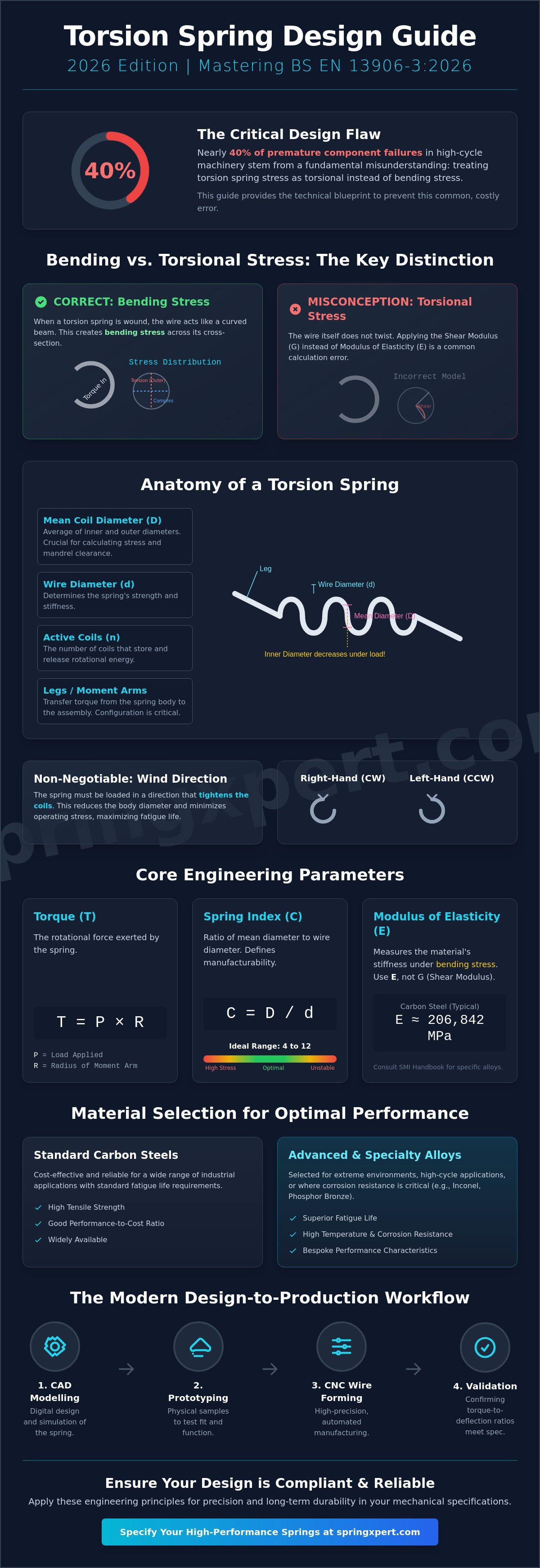
Miscalculating the distinction between bending and torsional stress accounts for nearly 40% of premature component failures in high-cycle industrial machinery. Engineers frequently find that achieving precise torque at specific deflection angles is the most technical variable in any assembly. It's a common challenge that often leads to over-engineering or unexpected mechanical fatigue. This torsion spring design guide 2026 provides the technical blueprint you need to master material standards and calculate exact torque requirements for the next generation of UK manufacturing. You will learn to navigate the updated BS EN 13906-3:2026 standards while optimizing your performance-to-cost ratio. We will examine specific alloy selections for extreme fatigue life and provide a systematic framework for specifying high-performance springs that meet rigorous industrial demands. By following these established engineering principles, you can ensure your designs remain compliant and reliable in increasingly complex B2B applications. This guide serves as a technical foundation for engineers who prioritize precision and long-term durability in their mechanical specifications.
Key Takeaways
- Understand the mechanical distinction between bending and torsional stress to ensure component durability under specific rotational loads.
- Utilise our torsion spring design guide 2026 to master the precise engineering formulas for torque and deflection required for high-performance industrial applications.
- Evaluate the performance characteristics of standard carbon steels against advanced alloys to optimise tensile strength for bespoke requirements.
- Identify how specific leg configurations and lever arm lengths impact mechanical integration and effective torque delivery in your assemblies.
- Learn the technical transition from CAD modelling to CNC wire forming to accurately validate torque-to-deflection ratios during the prototyping phase.
Fundamentals of Torsion Spring Mechanics and Terminology
A torsion spring is a helical component engineered to exert torque or store rotational energy. Unlike compression springs that resist axial force, these components operate through angular deflection. Within the framework of Torsion Spring Fundamentals, it's vital to recognize that the primary function involves the storage and controlled release of energy across a mechanical pivot. The assembly typically consists of a cylindrical body of wire, terminating in specific leg configurations that interface with mechanical housings or linkages.
Engineers must acknowledge a critical physical distinction: the wire in a torsion spring is subjected to bending stress rather than torsional stress. This distinction is central to this torsion spring design guide 2026. As the spring is wound, the wire acts as a curved beam; the internal forces are distributed across the cross-section as tensile and compressive stresses. Precision manufacturing ensures that the wire diameter and body diameter are optimized to handle these loads without exceeding the material's elastic limit.
Essential Nomenclature for Engineering Specifications
Accurate specification requires a firm grasp of standard industrial terminology. The Mean Coil Diameter is the average of the outer and inner diameters; it's a decisive factor when calculating clearance over supporting mandrels or shafts. Designers must account for the fact that the inner diameter decreases as the spring is loaded. Active coils in a torsion spring usually equal the total number of coils, though the length and orientation of the legs also influence the total angular deflection and rate.
Wind direction is a non-negotiable specification in any technical drawing. Springs are wound either clockwise (right-hand) or counter-clockwise (left-hand). This choice isn't arbitrary; it's dictated by the direction of the force being applied in the final assembly. Identifying the correct hand of wind ensures the spring functions within its intended mechanical parameters.
Torque vs. Bending Stress: The Designer’s Dilemma
When a torsion spring rotates, the wire undergoes a bending mode that creates a stress gradient. The inner fibre of the wire experiences the highest stress concentration because the radius of curvature is smallest at the internal surface. This peak stress often limits the maximum deflection a spring can safely achieve before suffering a permanent set or fatigue failure. High-tensile alloys are frequently selected to mitigate these risks in high-cycle applications.
The relationship between torque and stress is the foundation of this torsion spring design guide 2026. To maintain structural integrity and maximize service life, the wind direction must always follow the direction of the applied torque so that the spring coils tighten during operation. This ensures the material remains in a state of compression on the inner diameter and tension on the outer diameter, which is the most stable configuration for helical wire components.
Engineering Formulas for Torque, Rate, and Deflection
Precise torque calculation forms the foundation of any torsion spring design guide 2026. The fundamental formula for torque is T = P × R, where T represents torque, P is the load applied, and R is the radius of the moment arm. In high-performance UK manufacturing environments, engineers must calculate this value with extreme accuracy to ensure the component meets the specific load requirements of the assembly. The Modulus of Elasticity (E) is the primary material constant used in these calculations. For standard carbon steels, E is typically 206,842 MPa. This value determines the material's stiffness under bending stress. Because torsion spring wire is subjected to bending rather than torsion, E is used instead of the Shear Modulus (G). Designers should consult the Spring Manufacturers Institute (SMI) Handbook to verify exact E values for specialized alloys like Inconel or phosphor bronze. The number of active coils (n) inversely affects the angular spring rate. Increasing the coil count reduces the rate, making the spring more flexible. Conversely, fewer coils create a stiffer spring. The Spring Index (C), calculated as the ratio of mean diameter (D) to wire diameter (d), remains a critical metric for manufacturing feasibility. A Spring Index between 4 and 12 is ideal. Indices below 4 often lead to excessive tool wear and internal material stress, while indices above 12 can result in springs that lack structural stability during operation.Calculating Angular Spring Rate and Deflection
The angular spring rate (k) is determined by the formula: k = (E * d^4) / (10.8 * D * n). This formula provides the rate in Newton-millimetres per degree. For precision timing or aerospace applications, converting deflection from degrees to radians is often necessary for integration into complex mechanical models. In close-wound designs, friction between adjacent coils can cause a lag in response or "hysteresis." To mitigate this, designers often specify a small initial tension or a slight gap between coils.Stress Calculations and Fatigue Limits
The maximum bending stress (S) in a torsion spring is calculated using S = (32 * M) / (π * d^3). However, this doesn't account for the curvature of the wire. Engineers apply a stress correction factor, similar to the Wahl factor used in compression springs, to account for the increased stress on the inner diameter of the coil. In 2026, tighter manufacturing tolerances allow for more aggressive stress profiles without compromising reliability. These precise calculations ensure that the component operates within its elastic limit, preventing premature fatigue failure in demanding UK industrial cycles. For a detailed review of your specific requirements, you can consult our technical teamMaterial Selection and 2026 Performance Standards
Material choice dictates the operational ceiling of any mechanical system. For this torsion spring design guide 2026, engineers must distinguish between standard carbon steels and high-performance alloys to meet evolving industrial demands. While music wire (ASTM A228) remains a staple for high-stress applications due to its high tensile strength, the 2026 market increasingly requires materials that maintain performance in extreme environments. Tensile strength directly determines the maximum allowable torque; if the applied stress exceeds the elastic limit, the spring suffers permanent set, leading to assembly failure.
Environmental factors in the UK, such as high humidity in coastal regions or chemical exposure in industrial processing, necessitate a rigorous selection process. High-carbon steels are susceptible to rapid oxidation. Consequently, designers are pivoting toward alloys that offer inherent protection. For a broader perspective on how these choices impact different spring types, engineers can consult our guide on choosing materials for springs to ensure consistency across their mechanical assemblies.
High-Tensile Alloys and Stainless Steel Options
Type 302 and 316 Stainless Steel are the primary choices for corrosion-critical applications. Type 302 provides excellent strength through cold working, while Type 316 offers superior resistance to chlorides and acids. For high-fatigue or high-temperature environments exceeding 120°C, Chrome Silicon and Chrome Vanadium are the preferred alloys. These materials allow for higher working stresses than standard carbon steel. The Modulus of Elasticity (E) varies across these metals, typically around 210 GPa for carbon steels and 193 GPa for stainless steel. This variation must be accounted for in torque calculations to ensure the torsion spring design guide 2026 specifications are met with precision.
Surface Treatments and Protective Coatings
Surface treatments extend the service life of torsion springs by providing a barrier against atmospheric corrosion. Zinc plating remains popular for its sacrificial protection, while passivating is essential for stainless steels to remove surface contaminants and enhance the chromium oxide layer. Powder coating offers a robust aesthetic and functional finish, though it adds thickness that designers must account for in clearance tolerances.
- Zinc Plating: Cost-effective protection for carbon steel components.
- Passivation: Critical for maintaining the integrity of stainless steel alloys.
- Powder Coating: Provides high-impact resistance and custom colour coding for assembly identification.
A critical risk in the plating process is hydrogen embrittlement. This occurs when hydrogen atoms penetrate the metal during acid pickling or electroplating, leading to sudden, brittle fractures under load. To mitigate this, high-tensile springs must undergo a de-embrittlement baking process within hours of plating. For 2026, sustainability standards like REACH and RoHS are the baseline. We prioritise coatings that eliminate hexavalent chromium and other restricted substances to ensure environmental compliance across all UK and international projects.
Leg Configurations and Mechanical Integration
Legs serve as the physical interface between the stored energy in the coils and the external application. Common configurations include straight, offset, hinged, and hooked ends. Each style addresses a specific mechanical requirement. Straight legs are the most cost-effective for standard applications. Hooked or hinged ends provide more secure anchoring in high-vibration environments. Leg length is a primary variable in this torsion spring design guide 2026 because it defines the effective lever arm. A longer leg increases the moment arm. This reduces the input force required to achieve a specific torque value but increases the sweep of the deflection arc.
Engineers must account for the internal support provided by mandrels or arbours. As a torsion spring is loaded, the inner diameter decreases. If the arbour is too large, the spring will bind. This leads to premature fatigue or erratic torque delivery. A standard engineering practice is to maintain a clearance of at least 10% of the wire diameter at maximum deflection. This allows the spring to breathe during its duty cycle without friction-induced heat buildup.
- Straight Legs: Best for simple torque transfer and lower manufacturing costs.
- Offset Legs: Used to clear obstructions or align with specific mounting points.
- Hooked Ends: Essential for applications where the spring must remain captive under sudden load changes.
- Hinged Ends: Provide flexibility in the angle of engagement, reducing side-loading on the coil body.
Designing for Secure Attachment and Stability
Specifying the initial orientation of the legs is vital for assembly. Positions are defined as radial, tangential, or axial relative to the coil body. Proper alignment prevents "leg kick," which refers to the lateral displacement of the leg under load. Designers mitigate this by ensuring the leg remains in a guided track or by using custom-engineered seats. Every bend introduced into a leg creates a stress concentration point. To maintain a robust stress profile, engineers should specify a bend radius that's at least 1.5 times the wire diameter to avoid tensile failure at the transition point.
Double Torsion Springs: When to Use Them
A double torsion spring consists of two separate coil sections joined by a central bridge. This configuration provides a balanced load distribution and prevents the tilting that can occur with single torsion units. These components are ideal for applications requiring high torque within a restricted footprint, such as heavy-duty automotive hinges or industrial overhead doors. While they offer superior stability, they involve higher manufacturing costs. Producing these units requires advanced multi-axis CNC machinery. This often increases production time by 20% compared to single units, though the gain in mechanical equilibrium is often worth the investment.
For technical assistance with complex geometry, contact our team to discuss custom-engineered torsion solutions today.
Specifying Bespoke Torsion Springs for 2026
The transition from a theoretical model to a physical component requires absolute alignment between design intent and manufacturing capability. In the context of this torsion spring design guide 2026, the focus shifts from calculation to the practicalities of CNC wire forming. Modern production environments now utilise automated multi-axis forming centres that interpret vector data directly from engineering files. This integration reduces the margin for human error and ensures that the first production batch matches the digital master with sub-millimetre precision.
Prototyping remains a critical phase for validating torque-to-deflection ratios. Even with advanced software, physical testing accounts for variables like material grain orientation and subtle friction factors within the assembly. Validating these ratios early prevents costly tool adjustments during full-scale production runs. The Xpert approach prioritises technical collaboration, where our engineers work alongside your design team to refine tolerances before the first wire is cut.
The CAD-to-Component Workflow
SpringXpert utilises high-fidelity CAD files to drive our CNC production lines. We accept standard formats such as .STEP and .IGES to ensure that every bend and leg angle meets your specific requirements. Digital simulation plays a vital role here; we use stress analysis software to predict potential spring failure points before manufacturing begins. It's more efficient to identify a fatigue risk in a virtual environment than in a physical test rig. We encourage designers to consult with our engineering team early in the design cycle to optimise material selection and leg geometry for manufacturability.
Partnering with SpringXpert for Custom Solutions
With over 20 years of experience across high-specification industrial sectors, SpringXpert provides the stability required for complex B2B projects. We maintain a stock of over 20,000 standard products for immediate requirements, yet our core strength lies in bespoke engineering. Whether your project involves aerospace-grade alloys or high-volume automotive components, our facility is equipped to handle rigorous quality standards. Our processes are designed for transparency, providing clear data on tensile strength and load capacities for every custom order.
Manufacturing Quote Checklist
To receive an accurate quote based on this torsion spring design guide 2026, please provide the following technical data:
- Wire Diameter: Specified in mm to three decimal places.
- Material Grade: e.g., BS EN 10270-3 stainless steel or carbon steel.
- Mandrel Size: The diameter of the shaft the spring will work over.
- Leg Specifications: Lengths, bend angles, and any required hooks or loops.
- Torque Requirements: Required torque at specific deflection angles.
- Finish: Passivation, zinc plating, or powder coating requirements.
Precision is the foundation of industrial reliability. If your application demands specific performance characteristics that standard components cannot meet, a custom-engineered solution is the most viable path forward. Contact our engineering team for a bespoke torsion spring design consultation to discuss your 2026 project requirements.
Optimising Your Torsion Spring Specifications for 2026
Successful mechanical integration depends on the precise alignment of torque calculations, material tensile strength, and leg geometry. This torsion spring design guide 2026 establishes the framework for achieving these tolerances within modern industrial environments. Selecting the correct alloy and defining exact deflection limits are critical steps that prevent premature component failure and ensure operational stability in high-cycle applications.
SpringXpert supports these engineering requirements through ISO 9001 certified manufacturing processes and rigorous quality control. We've built over 20 years of bespoke engineering expertise, allowing us to solve complex torque challenges for diverse B2B sectors. Whether you require a single prototype or a large-scale production run, we provide national UK delivery on all standard and custom orders. Our focus remains on delivering industrial reliability through technical precision and verified manufacturing standards.
We're ready to assist with your specific design parameters and provide the engineering clarity your project demands. It's time to move your designs from the screen to the production line with a partner committed to technical excellence.
Request a Technical Quote for Custom Torsion Springs
Frequently Asked Questions
How do I calculate the torque of a torsion spring?
Torque is calculated by multiplying the spring rate by the angle of deflection in degrees or radians. The formula for the spring rate is (E * d^4) / (10.8 * D * N), where E represents the Modulus of Elasticity, d is the wire diameter, D is the mean coil diameter, and N is the number of active coils. For standard carbon steel used in the UK, E is typically 210 GPa. This calculation is a fundamental component of our torsion spring design guide 2026.
What is the difference between a single and double torsion spring?
A single torsion spring consists of one coil body with two legs, while a double torsion spring features two separate coil sections joined by a central bridge. Double torsion designs function as two springs working in parallel, which effectively doubles the torque output for the same deflection. These are frequently utilised in UK automotive and heavy machinery sectors where balanced load distribution is required. Single versions are more efficient for standard hinge applications.
Why do torsion springs fail prematurely in industrial applications?
Premature failure usually stems from fatigue, hydrogen embrittlement, or excessive friction against a supporting mandrel. Data indicates that 22% of industrial spring failures result from stress corrosion cracking in environments with high humidity. If a spring's operating stress exceeds 45% of its minimum tensile strength, the risk of permanent set increases. Maintaining a 15% safety margin below the elastic limit is a standard engineering practice to extend component life.
Can a torsion spring be used in both directions of rotation?
You shouldn't use a torsion spring in both directions because it's designed to function only in the direction that winds the coils tighter. Winding a spring in the opposite direction increases the coil diameter and introduces stresses that the material isn't configured to handle. This practice can reduce the fatigue life by as much as 50%. You must specify either clockwise or anti-clockwise winding during the design phase to ensure mechanical reliability.
What is the maximum allowable stress for a stainless steel torsion spring?
The maximum allowable stress for Grade 302 or 304 stainless steel is generally 40% to 45% of the wire's minimum tensile strength. For a 2.0mm wire with a tensile strength of 1,600 MPa, the design stress shouldn't exceed 720 MPa. While Grade 316 offers superior corrosion resistance for British maritime applications, it typically possesses 10% less mechanical strength than Grade 302. Accurate stress analysis prevents the spring from taking a permanent set during operation.
How does the number of coils affect the spring rate?
The spring rate is inversely proportional to the number of active coils in the body. If you double the number of coils, the spring rate is reduced by exactly half. This relationship is critical when following a torsion spring design guide 2026 to achieve specific torque requirements. Increasing the coil count allows for greater angular deflection by distributing the stress over more material, but it simultaneously lowers the torque delivered per degree of movement.
What information is needed to order a custom torsion spring?
You need to provide the wire diameter, mean coil diameter, number of coils, leg lengths, and the specific material grade. It's also vital to specify the required torque at a given angle and the winding direction. Adhering to BS EN 10270 standards for tolerances ensures the component meets industrial requirements. Providing a 3D CAD file or a detailed technical drawing can reduce manufacturing lead times by 15% by eliminating specification ambiguities.
Should a torsion spring be supported by a mandrel?
Yes, you should support a torsion spring with an internal mandrel to maintain its position and prevent buckling under load. The mandrel diameter should typically be 90% of the spring's internal diameter at its maximum deflection point. If the clearance is too tight, the spring will bind on the rod as the coils contract during winding. This binding creates unnecessary friction and heat, which eventually leads to localized wear and structural failure.