

Understanding Clock Springs: A Technical Guide to Spiral Torsion Components
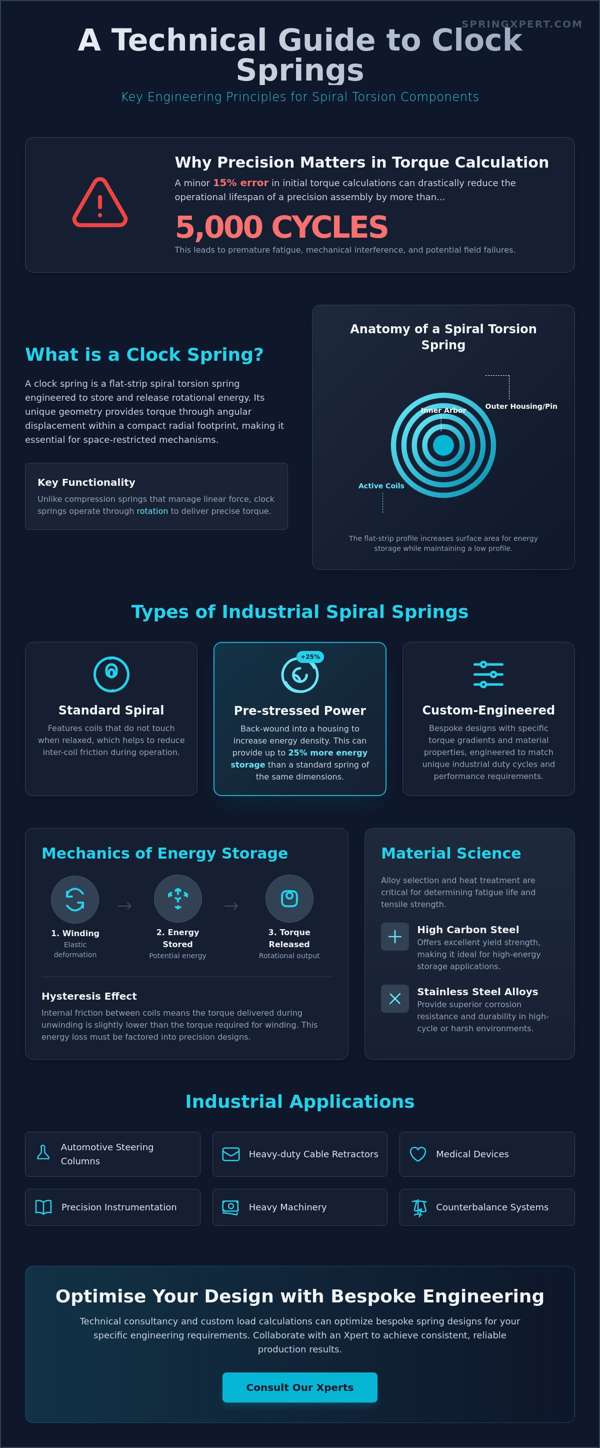
A 15% error in initial torque calculations often reduces the operational lifespan of a precision assembly by more than 5,000 cycles. You likely recognize that selecting an inappropriate spiral torsion component leads to premature fatigue or mechanical interference. It's a frequent challenge for engineers to distinguish between light duty horological mainsprings and the robust industrial clock springs required for high torque applications. Misidentifying these components can cause significant delays in the prototyping phase or lead to failures in the field.
This guide provides the technical data necessary to evaluate material options, calculate torque requirements for restricted spaces, and specify exact tolerances for your UK manufacturing projects. As your engineering partner, we focus on the physical realities of spring performance. We'll examine the mechanical properties of high carbon steel and stainless alloys, the physics of spiral energy storage, and the specific criteria for ensuring long term reliability in high cycle environments. You'll gain the clarity needed to determine if these bespoke solutions fit your design parameters and how to collaborate with an Xpert to achieve consistent production results.
Key Takeaways
- Understand the fundamental physics of how flat-strip spiral torsion components store rotational energy within a compact footprint.
- Analyse the torque-to-rotation relationship of clock springs to ensure precise energy release in high-tolerance mechanical assemblies.
- Identify how specific alloy selection and heat treatment processes determine the fatigue life and tensile strength of industrial components.
- Evaluate the integration of spiral torsion technology into retraction mechanisms and counterbalance systems for enhanced operational performance.
- Learn how technical consultancy and custom load calculations can optimise bespoke spring designs for specific engineering requirements.
What is a Clock Spring? Defining Spiral Torsion Components
A clock spring is a flat-strip spiral torsion spring engineered to store and release rotational energy within a restricted radial footprint. These components are manufactured by winding a rectangular cross-section material into a flat spiral. This geometry allows the spring to provide torque through angular displacement, making it an essential solution for mechanisms requiring compact energy storage. While the Clockspring is widely recognized for its role in automotive steering columns, the term encompasses a broad range of industrial spiral torsion components used in heavy machinery and precision instrumentation.
Terminology in the spring industry often overlaps. You'll hear these components referred to as spiral springs, power springs, or mainsprings. A power spring typically involves a larger number of coils housed within a container to provide high torque over many revolutions. A mainspring refers specifically to the energy source in horology. In contrast to compression springs that manage axial loads through linear deflection, clock springs operate through rotation. This fundamental difference dictates their application in bespoke assemblies where torque, rather than linear force, is the primary requirement.
The Anatomy of a Spiral Torsion Spring
The defining characteristic of a clock spring is its flat-strip material profile. Using flat wire instead of round wire increases the surface area for energy storage while maintaining a low profile. The assembly relies on two critical connection points: the inner arbor and the outer housing. The arbor serves as the central shaft that winds the spring, while the housing or outer pin secures the exterior tail.
Within the assembly, engineers distinguish between active and dead coils. Active coils are the portions of the strip that flex and store energy during winding. Dead coils are the segments immediately adjacent to the attachment points that don't contribute to the spring rate. Our Xpert design process ensures that the transition between these zones is managed to prevent stress concentrations that could lead to premature fatigue failure.
Clockwork vs. Industrial Spiral Springs
The "clock spring" name persists because of its origins in 18th-century horology, where low-torque springs powered timepieces. Modern industrial applications require significantly higher performance levels. Industrial versions often utilize high-tensile stainless steel alloys to handle torque requirements exceeding 50 Newton-metres in heavy-duty retraction systems.
- Standard Spiral Springs: These feature coils that don't touch when the spring is relaxed, reducing friction.
- Pre-stressed Power Springs: These are back-wound into a housing to increase energy density. A pre-stressed spring can offer up to 25% more energy storage than a conventional spiral spring of the same size.
- Custom-Engineered Solutions: SpringXpert develops bespoke clock springs with specific torque gradients to match unique industrial duty cycles.
Whether you're developing a medical device or a heavy-duty cable retractor, the choice of alloy and winding tension is critical. We invite you to engage with our technical team to discuss how our custom-engineered spiral torsion components can meet your specific torque tolerances and durability standards.
The Mechanics of Spiral Spring Energy Storage
Winding a clock spring involves the elastic deformation of a flat metal strip, typically made from high-tensile carbon or stainless steel. As the strip coils tighter around a central arbor, it accumulates potential energy. This energy density is governed by the material's yield strength and the geometric profile of the strip. Unlike linear components that follow a basic displacement-to-force ratio, the torque-to-rotation relationship in these springs becomes complex as the coils begin to interact or "bottom out" against one another.
Internal friction between adjacent coils creates a phenomenon known as hysteresis. This means the torque delivered during the unwinding cycle is slightly lower than the torque required during the initial winding. In precision applications, engineers must account for this energy loss to ensure consistent performance. While extension springs provide force through axial tension along a straight line, clock springs deliver rotational torque through a circular path, making them indispensable for compact, oscillating mechanisms.
Calculating Torque and Deflection
Engineers determine the torque (M) of a spiral spring using the standard formula: M = (Ebt³α) / (12L). In this equation, E represents the Modulus of Elasticity, b is the strip width, t is the thickness, α is the angular deflection in radians, and L is the total developed length of the material. While increasing the width (b) provides a linear increase in torque, the thickness (t) has a much more dramatic impact because it's a cubed value in the calculation. The torque capacity of a spiral spring is directly proportional to the cube of the strip thickness. Adjusting the total length (L) allows for a finer calibration of the spring rate, providing a softer or stiffer feel depending on the industrial requirement.
Open-Wound vs. Close-Wound Designs
Open-wound designs feature deliberate gaps between each coil. This configuration eliminates internal friction and ensures a smooth, linear torque curve, but it generally limits the total rotation to less than 360 degrees. These are preferred for sensitive instrumentation where any "jump" in torque caused by coil friction would compromise accuracy.
Close-wound designs, or power springs, allow the coils to touch and slide against each other. This allows for massive energy storage and a high number of rotations within a restricted diameter. For example, a steering column control module utilizes these compact designs to maintain electrical continuity over several full rotations of a steering wheel. When choosing between these designs, consider the total degrees of travel; if the application exceeds one full turn, a close-wound power spring is usually the standard choice. You can discuss your specific rotational requirements with our technical team to identify the most durable custom-engineered solution for your assembly.
Material Science and Manufacturing Specifications
Material selection is the primary determinant of fatigue life in clock springs. These components operate under constant cyclic stress, where the strip material must provide high tensile strength without becoming brittle. The manufacturing process begins with precision slitting of the spring steel to the required width. This stage is critical because any irregularities on the strip edge act as stress concentrators. Precision deburring or edge conditioning is applied to remove micro-burrs, preventing the development of stress fractures during high-tension winding. Following the forming process, controlled heat treatment is essential to set the spring's memory and relieve internal stresses. While disc springs are engineered for extremely high axial loads over short travel distances, clock springs are designed for rotational energy storage across multiple turns. Engineers often rely on spiral torsion spring design equations to calculate the exact relationship between material thickness, strip width, and the resulting torque output.Common Alloys for Industrial Clock Springs
- High-carbon spring steel: Often specified as BS EN 10132-4 grades. It's a cost-effective solution with excellent strength, though it requires protective coatings to prevent corrosion in UK environments.
- Stainless steel (301/302): These grades are standard for medical devices and marine hardware. They offer high fatigue resistance and natural corrosion protection without additional plating.
- Exotic alloys: Materials like Inconel or Elgiloy are reserved for aerospace or North Sea oil and gas applications. These alloys maintain their mechanical properties at temperatures exceeding 300°C.
Specifying Tolerances and Finishing
Defining precise tolerances is vital for consistent torque delivery. Industrial specifications usually define torque at specific degrees of rotation, such as ±10% at 360 degrees. Surface finishes play a secondary but critical role in durability. Zinc plating or passivation provides a barrier against oxidation, while dry-film lubricants or specialized greases reduce internal friction between the coils. This lubrication is necessary to prevent "stiction" and wear as the clock springs expand and contract during operation. Every custom-engineered solution we provide undergoes rigorous testing to ensure these specifications meet the operational reality of the client's assembly.
Industrial Applications and Practical Implementation
Clock springs are essential for compact energy storage in modern mechanical assemblies. These components provide the necessary torque for retraction mechanisms and counterbalances where linear springs would prove too bulky. In the UK manufacturing sector, engineers rely on these spiral torsion components to maintain cable tension and ensure controlled return cycles in high-frequency applications. Their ability to deliver consistent force over multiple rotations makes them indispensable for space-constrained designs.
Beyond the Clock: Modern Engineering Uses
The automotive industry represents the highest volume of clock springs usage. They facilitate the electrical connection between the steering wheel and the steering column, allowing for constant rotation without damaging wiring for airbags or horn controls. They also power seatbelt retractors to ensure the webbing returns to its housing with consistent tension. In the medical field, these springs are integrated into drug delivery pens and surgical tool return mechanisms where precision is a regulatory requirement. Aerospace applications include valve actuators and instrumentation return springs where components must perform reliably under extreme temperature fluctuations and vibration.
Installation and Maintenance Best Practices
The primary safety misconception in spring handling is that low-torque components pose minimal risk. This is a dangerous assumption. A wound spring stores significant potential energy; an uncontrolled release can cause lacerations or damage to surrounding housing. Technicians must use specialised winding tools and maintain a firm grip on the outer and inner attachment points during the entire installation process.
Maintenance focuses on identifying "setting," which occurs when the spring loses its original profile due to exceeding its elastic limit. Engineers should monitor for a drop in torque output. If the measured force deviates by more than 10% from the original design specification, the spring has likely reached its fatigue limit. While some heavy-duty industrial springs allow for minor tension adjustments, most precision components require full replacement once they have taken a permanent set to ensure the safety of the assembly.
Engineering Integration Checklist:
- Define the required torque at both minimum and maximum deflection points.
- Calculate the anticipated cycle life based on material fatigue limits.
- Verify housing clearances to prevent edge friction and premature wear.
- Select alloys based on environmental factors like corrosion or heat.
- Confirm the arbor and outer casing attachment methods are secure.
Precision manufacturing ensures that every component meets the strict tolerances required for safety-critical systems. For bespoke engineering support and custom manufacturing, connect with the technical team at SpringXpert to optimise your assembly design.
Bespoke Engineering: Designing Custom Clock Springs
SpringXpert provides a structured methodology for manufacturing custom clock springs. Our process begins with a technical consultancy phase where we evaluate material properties against specific operational demands. Technical specialists analyze tensile strength and fatigue limits to ensure the chosen alloy meets industrial performance benchmarks. Our engineers perform precise load calculations to determine the exact torque output required for your application. This data-driven approach eliminates guesswork and ensures that every component performs within its intended tolerances. We transition from initial CAD prototyping to full-scale CNC production, maintaining high repeatability across thousands of units.
The Custom Design Workflow
To initiate a custom build, clients provide three critical parameters: spatial constraints, required torque, and target cycle life. We translate these inputs into detailed CAD models for initial validation. Prototyping follows, allowing your team to test mechanical performance in a real-world environment before committing to mass production. This stage is vital for identifying potential stress points or friction issues within the spiral assembly. We offer tiered pricing for industrial runs, where costs are optimized based on volume and material complexity. Lead times are clearly defined at the outset to align with your project milestones. This systematic workflow ensures that the final clock springs meet the exact mechanical requirements of your assembly.
Partnering with a UK Specialist
Choosing a UK-based manufacturer provides distinct advantages in quality control and supply chain stability. SpringXpert leverages 20 years of engineering experience to maintain tight tolerances across every production batch. We transition seamlessly from validated prototypes to full-scale CNC production, utilizing advanced machinery to ensure repeatability. This domestic presence means faster response times and direct access to our technical team. We act as an extension of your engineering department, providing the specialized knowledge needed for high-performance components. Our facility is equipped to handle complex material requirements, including high-carbon steels and corrosion-resistant alloys. This expertise ensures that your components withstand rigorous industrial environments. It's an approach that prioritizes longevity and functional reliability over generic solutions. Consult our engineering team for your bespoke clock spring requirements to begin your project.
Optimising Industrial Performance with Precision Engineering
Selecting the right clock springs requires a detailed understanding of torque requirements, fatigue life, and material constraints. These components provide vital energy storage within tight spatial envelopes, making precise manufacturing tolerances essential for long-term reliability. Engineers must balance tensile strength with environmental factors to ensure consistent performance in demanding UK industrial applications. It's often the difference between a system that fails prematurely and one that maintains operational integrity over millions of cycles.
SpringXpert supports your project through every stage of the design and procurement process. We operate an ISO 9001 certified manufacturing facility to guarantee quality across our entire range. If your requirements are immediate, we've over 20,000 standard products in stock for rapid delivery. For unique specifications, our UK technical team offers bespoke engineering support to develop custom solutions tailored to your exact mechanical needs. Our focus remains on providing the technical depth required to solve complex motion control challenges.
Take the next step in your engineering project by contacting our specialists today. Request a technical consultation for custom clock springs to discuss your specific torque and material requirements with our team. We look forward to partnering with you on your next high-precision build.
Frequently Asked Questions
What is the difference between a clock spring and a power spring?
Clock springs differ from power springs primarily in their coil configuration and housing requirements. A clock spring features open, non-contacting coils that prevent friction during operation, while a power spring has contacting coils usually stored within a circular case. This design allows clock springs to deliver consistent torque over a specific angular rotation, typically less than 360 degrees. Power springs are better suited for applications requiring high energy storage and multiple rotations.
Can clock springs be used for continuous rotation?
Clock springs can't be used for continuous rotation because their mechanical design relies on a fixed inner and outer attachment point. The spiral strip winds or unwinds within a defined angular range, usually limited to 10 or 20 turns depending on the material thickness and arbor size. Attempting continuous rotation will lead to plastic deformation or immediate mechanical breakage. For applications requiring 360-degree movement, engineers should specify slip rings or rotary joints instead.
How do I measure an existing clock spring for replacement?
You measure an existing clock spring by recording the material width, strip thickness, and the number of active coils. Use a digital caliper to verify the inner diameter of the arbor and the maximum outer diameter when the component's in a relaxed state. Precise measurements are critical because a 0.05mm variance in thickness can alter torque output by 15%. Always specify the material grade, such as 301 stainless steel or high-carbon spring steel.
What causes a clock spring to fail prematurely?
Premature failure in clock springs often results from over-stressing the material beyond its elastic limit or operating in corrosive environments without adequate plating. Surface imperfections or burrs on the strip edges act as stress concentrators, leading to fatigue cracks after as few as 5,000 cycles. Environmental factors like moisture or chemical exposure accelerate hydrogen embrittlement. Ensuring the spring operates within its calculated 80% stress range significantly extends its functional lifespan.
Are clock springs available in stainless steel for medical use?
We manufacture clock springs using medical-grade stainless steel alloys such as Type 301 and Type 316. These materials provide the necessary corrosion resistance for surgical instruments and diagnostic equipment that undergo frequent sterilisation. In the UK, medical components must meet ISO 13485 standards to ensure traceability and material purity. Our custom-engineered solutions maintain tight tolerances to ensure repeatable performance in precision-critical healthcare applications where reliability is the primary requirement.
How much torque can a standard industrial clock spring provide?
Torque output for industrial clock springs varies based on dimensions, but standard units typically range from 0.1 Nm to over 50 Nm. A spring with a 50mm diameter and 1.5mm thickness might provide approximately 5 Nm of torque at maximum deflection. Because torque's proportional to the material width and the cube of the thickness, small adjustments to the strip profile result in significant performance changes. Engineers must calculate the required torque at both the start and end positions.
What is the typical fatigue life of a high-quality spiral spring?
A high-quality clock spring generally achieves a fatigue life between 10,000 and 1,000,000 cycles depending on the stress levels applied. When the design limits stress to 50% of the material's minimum tensile strength, the component can often exceed 500,000 cycles. In contrast, springs designed for maximum energy density might only last 20,000 cycles. We use fatigue testing data and FEA modelling to predict longevity based on specific British Standard (BS EN) material specifications.