

Spring Fatigue Life Explained: An Engineer’s Guide to Durability (2026)
A single micro-fracture, often invisible to the naked eye, accounts for approximately 80% of mechanical spring failures in high-cycle UK industrial machinery. For a design engineer at a Midlands manufacturing facility, these unpredictable breakdowns represent more than just downtime; they signify a failure in precision stress calculation. You understand that balancing component cost against long-term durability is a constant challenge, especially when standard data sheets fail to account for variable operating temperatures or corrosive environments. This guide ensures the concept of spring fatigue life explained moves from theoretical complexity to practical application in your 2026 projects.
We provide a reliable framework for specifying spring life with absolute confidence. You'll learn how to use S-N curves and Goodman diagrams to predict service life accurately and prevent premature failure in bespoke mechanical systems. We'll also examine how specific material choices and shot-peening processes extend cycle life by up to 300% in demanding applications. This technical overview equips you with the data needed to make informed engineering decisions that prioritise stability and industrial reliability.
Key Takeaways
- Define the critical thresholds between plastic deformation and catastrophic fracture to establish precise operational limits for your mechanical components.
- Master the analytical use of S-N Curves and Goodman Diagrams as spring fatigue life explained within this guide provides the framework for predicting component reliability.
- Recognise how environmental corrosion and surface defects act as catalysts for premature failure in demanding UK industrial settings.
- Discover how to specify shot peening and optimise coil geometry to introduce compressive residual stresses and significantly extend cycle counts.
- Explore the benefits of technical collaboration for bespoke spring designs that adhere to stringent BS EN manufacturing standards.
What is Spring Fatigue Life? Defining the Limits of Elasticity
In precision engineering, fatigue life represents the total number of stress cycles a component sustains before structural failure occurs. It's a metric critical for maintenance schedules in UK industrial facilities where machinery often operates 24 hours a day. Understanding spring fatigue life explained through the lens of durability helps engineers avoid unplanned downtime and manage asset lifecycles effectively. While a spring might seem robust, every compression or extension cycle causes internal changes to the material's grain structure.
Engineers distinguish between static loading and cyclic loading. Static loading involves a constant force, such as a heavy weight resting on a support spring. Cyclic loading involves the repeated application and release of energy, which is standard in British automotive assembly lines or high-speed packaging machinery. When a spring is pushed beyond its operational capacity, it doesn't always break immediately. It might first "take a set," which is a form of plastic deformation where the spring loses its original free length. This differs from catastrophic fracture, where the material physically separates and causes a total mechanical stoppage. The fatigue limit is the stress level below which failure is unlikely to occur regardless of the number of cycles.
The Mechanics of Cyclic Stress
Failure begins at the molecular level long before a visible break appears. Microscopic cracks often initiate at points of high stress concentration, such as surface scratches, tool marks, or material inclusions. This process, known as fatigue in materials science, progresses through a propagation phase where the crack expands with every load application. When a British maintenance technician inspects a production line, they might not see these tiny fissures until they reach a critical size. In most applications, compression springs experience maximum stress on the inner diameter of the coils. Extension springs are inherently more vulnerable at the hooks; the geometry of the loop creates significant stress risers compared to the uniform body of the spring.
Infinite Life vs. Finite Life Designs
Engineering specifications usually categorise durability into two distinct tiers based on the intended application. Infinite life refers to designs capable of exceeding 10 million cycles without failure. This is the standard for critical components like automotive valve springs or aerospace actuators. Finite life designs, which might be rated for 100,000 cycles, are acceptable trade-offs when a component is part of a seasonal machine or is easily replaceable during scheduled UK plant shutdowns. Most industrial compression springs are rated based on their stress range and specific material grade to ensure they meet these requirements. Choosing a finite life design can be a strategic choice to reduce material costs or weight in non-critical systems, provided the replacement interval is strictly managed by the engineering team.
The Engineering Science: S-N Curves and Goodman Diagrams
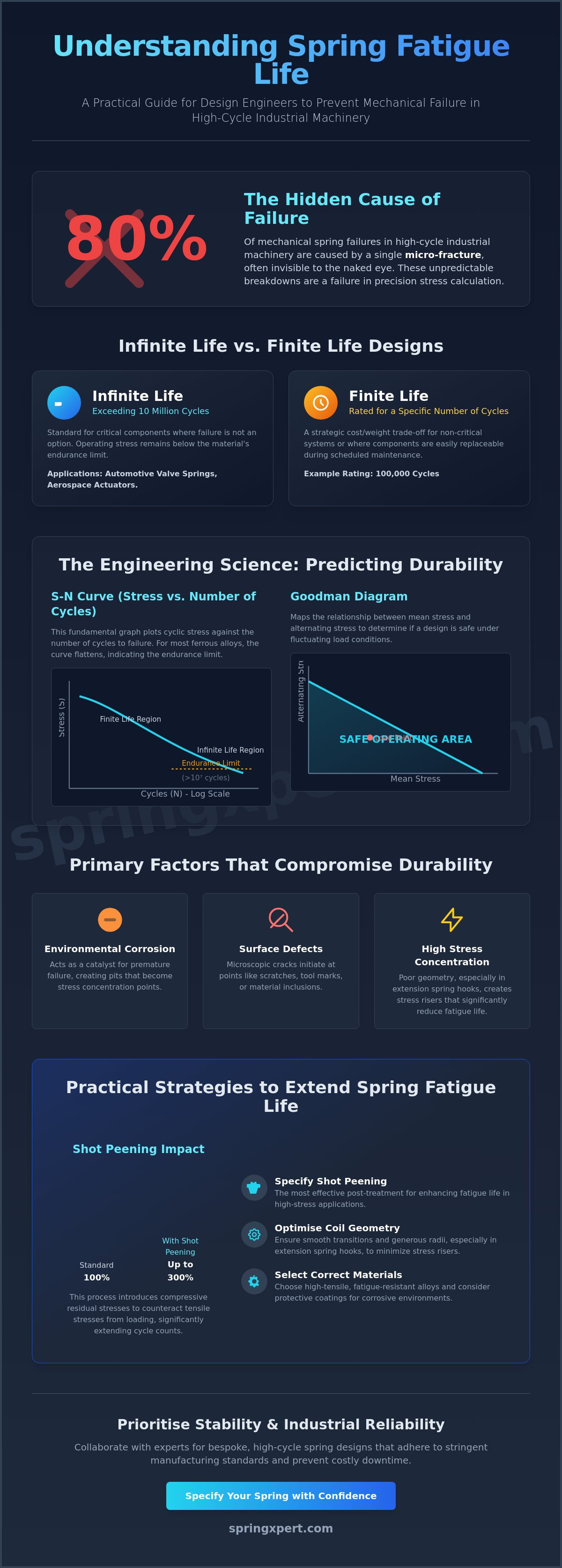
The S-N curve serves as the fundamental graph for fatigue testing. It plots cyclic stress amplitude against the number of cycles to failure on a logarithmic scale. For most ferrous alloys used in UK manufacturing, the curve flattens after 10,000,000 cycles. This flat region indicates the endurance limit. If the operating stress remains below this threshold, the component theoretically possesses infinite life. Understanding these plots is the first step in having spring fatigue life explained for practical application.
Engineers use the Goodman Diagram to determine if a design is safe under specific loading conditions. This tool maps the relationship between mean stress and alternating stress. It's essential because springs rarely operate under constant loads. Instead, they fluctuate between a minimum and maximum stress state. To achieve high reliability, the B-10 life metric is applied. This identifies the specific point where 10% of a spring population is expected to fail. Designing for B-10 ensures that 90% of your components exceed the required service duration in the field.
Interpreting the Goodman Diagram for UK Industry
Plotting load points requires calculating the mean stress and the stress range. When a point falls near the 1,000,000 cycle line, designers must apply conservative safety factors, often exceeding 1.5. This accounts for manufacturing variations and surface imperfections. In high-speed UK production lines, harmonic motion can cause the spring to vibrate at its natural frequency. This resonance increases the actual alternating stress beyond the calculated values, potentially shifting a safe design into the failure zone. Our Xpert analysis helps engineers validate these calculations before tooling begins.
The Role of Tensile Strength in Fatigue Resistance
A material's fatigue limit is directly proportional to its ultimate tensile strength (UTS). Higher UTS generally allows for a higher allowable stress range. UK-sourced high-carbon steels, such as those meeting BS EN 10270-1 standards, offer excellent performance for standard cyclic work. However, alloy steels like chrome silicon are preferred for high-stress applications due to their superior resistance to relaxation. The spring fatigue life explained in technical manuals often relies on these specific material properties.
Consider a senior engineer at a Midlands-based automotive plant. He reviews material certificates for a new batch of valve springs. He checks the chemical composition and tensile data to ensure the batch matches the design's fatigue requirements. This verification process is vital for maintaining bespoke spring performance across large production runs. Precise material selection prevents premature failure in critical infrastructure. It's a standard procedure that ensures every component meets the rigorous demands of British industrial standards.
Primary Factors That Compromise Spring Durability
Achieving a reliable spring fatigue life explained through engineering data requires a thorough understanding of the stressors that degrade metal components. While peak load is a common design focus, the stress range is the primary driver of failure. This represents the difference between the minimum and maximum stress levels during a cycle. A spring operating between 40% and 80% of its yield strength will often fail sooner than one operating between 10% and 50%, even though the latter reaches a lower peak. High stress ranges accelerate the propagation of microscopic cracks across the wire cross-section.
Surface integrity is equally vital. Minor nicks, tool marks, or longitudinal seams as small as 0.02mm can act as stress risers. These imperfections concentrate mechanical energy, providing a starting point for fatigue cracks. Industrial environments also introduce temperature variables. When carbon steel springs operate in environments exceeding 120°C, they become susceptible to creep. This thermal stress causes a gradual loss of load-bearing capacity, which shifts the operational geometry and alters the fatigue profile of the entire system.
Environmental and Chemical Stressors
Oxidation is a relentless catalyst for premature failure in British manufacturing plants. Moisture and salt spray in coastal UK regions lead to pitting corrosion. These pits serve as initiation sites for cracks. During the finishing stage, hydrogen embrittlement is a specific risk. This occurs when hydrogen atoms enter the steel during acid pickling or electroplating, making the alloy brittle. To mitigate this, engineers often specify de-embrittlement baking within two hours of plating. For specific environmental considerations, refer to our guide on extension springs to select the correct protective coatings.
Mechanical Misalignment and Friction
Improper installation frequently leads to side-loading, where the force isn't applied along the central axis of the spring. This creates non-uniform stress distribution, overloading one side of the coils. In long compression springs, a lack of internal or external guidance causes buckling. When a spring bows, the lateral friction against a housing or rod generates heat and physical wear. British maintenance teams often utilise end-grinding to ensure at least 270 degrees of square bearing surface. This precision prevents the spring from "walking" or tilting, which ensures the load stays axial and the fatigue life remains predictable. Accurate alignment can improve cycle life by up to 30% in high-speed industrial applications.
Practical Strategies to Extend Spring Fatigue Life
Extending component longevity requires a meticulous approach to both geometry and surface integrity. Engineers can significantly lower the operating stress range by increasing the wire diameter or adjusting the active coil count. These modifications redistribute the mechanical load across a larger volume of material, which directly influences the spring fatigue life explained in technical specifications. Reducing the stress at the maximum operating point is the most effective way to prevent premature crack initiation.
Material selection serves as the foundation for durability. For high-frequency applications, Chrome Silicon (CrSi) alloys are the industry standard. These materials offer superior resistance to relaxation and higher tensile strength compared to standard carbon steels. Implementing a rigorous maintenance schedule is also essential. Technicians should inspect for surface abrasions, corrosion pits, or fretting wear every 500,000 cycles. Even minor surface defects act as stress concentrators that can lead to rapid catastrophic failure.
The Power of Shot Peening
Shot peening is a cold-working process where the spring surface is bombarded with spherical steel shot or ceramic media. This high-velocity impact creates a uniform layer of compressive residual stress on the wire skin. This layer acts as a barrier, 'closing' microscopic surface cracks and preventing them from propagating under tensile load. Industrial data indicates that shot peening can increase fatigue life by 200% to 300% in high-stress environments. It hardens the surface and removes small manufacturing imperfections that typically serve as failure points.
Design Offsets and Pre-Setting
Pre-setting, often referred to as 'removing the set' or cold pressing, involves compressing a spring to its solid height during the manufacturing stage. This process induces beneficial internal stresses that stabilise the spring length and prevent further settling during service. In a typical British precision workshop, a white British technician will use a calibrated hydraulic press to verify that each component meets its specified free height after the pre-setting cycle. This ensures the spring maintains its load-bearing characteristics over millions of cycles.
In scenarios where space is limited but loads are extreme, engineers often transition from traditional coils to disc springs. These components can be arranged in various stack configurations to manage high forces while keeping the individual stress levels within safe fatigue limits. Proper stacking allows for a modular approach to durability, enabling the system to absorb high energy without exceeding the material's elastic limit.
If your application requires bespoke durability testing, contact our engineering team for a technical consultation.
Collaborating with SpringXpert for Bespoke High-Cycle Solutions
SpringXpert operates through a technical consultancy model we call the 'Xpert' approach. We don't just manufacture components; we partner with your design team to ensure every custom spring meets the specific stresses of its environment. Having the spring fatigue life explained in technical terms is only the beginning. Our role is to convert that theory into a physical component that survives millions of cycles without deformation. We assist clients in navigating the complex trade-offs between exotic alloys and standard carbon steels to balance unit costs with strict fatigue requirements. This ensures your project stays within budget while meeting safety-critical performance targets.
- Technical consultancy for bespoke spring geometry and coil configuration.
- Full compliance with BS EN 13906-1 and ISO 9001 quality standards.
- Direct access to UK-based engineering expertise for rapid prototyping cycles.
- Material selection focused on fatigue resistance, tensile strength, and corrosion protection.
From CAD Design to Industrial Reality
Our engineering team in Redditch uses advanced simulation software to predict fatigue behaviour before production begins. This process identifies high-stress regions in the coil geometry that might lead to premature failure. We utilize precision CNC manufacturing to ensure every batch matches the digital model exactly. Engineers are encouraged to submit their specific load requirements and operating temperatures for review. We provide a bespoke fatigue analysis that quantifies the expected lifespan of the component under real-world conditions. This data-driven approach removes the guesswork from the design phase and provides a clear roadmap for industrial implementation.
Why UK Manufacturing Matters for Fatigue Reliability
Traceability is the foundation of fatigue reliability. We source high-grade alloys from verified UK suppliers, ensuring that material impurities don't compromise the spring's integrity. When you call our technical department, you'll speak directly with an experienced British engineer who understands the nuances of UK industrial regulations. This professional, matter-of-fact dialogue ensures that mission-critical components are designed for durability rather than just price. Our UK-based engineering support allows for rapid prototyping, often delivering test samples 50% faster than international alternatives. This proximity ensures that your production schedule remains on track while maintaining the highest levels of precision manufacturing. We position ourselves as the primary partner for firms requiring components that withstand the rigours of 24/7 industrial operations.
Achieving Mechanical Durability Through Technical Precision
Ensuring long-term reliability in mechanical systems relies on a rigorous understanding of spring fatigue life explained through S-N curves and strict material tolerances. Engineers must prioritise the relationship between mean stress and alternating stress to prevent premature structural failure. By implementing precise Goodman diagram analysis and selecting high-grade alloys, you'll ensure your components withstand the millions of cycles required in modern UK industrial applications.
SpringXpert delivers this level of reliability from our ISO 9001 certified manufacturing facility in the United Kingdom. Our dedicated team of British engineering specialists leverages over 20 years of technical expertise to solve complex fatigue challenges. You've got immediate access to more than 20,000 standard products, and we provide dedicated custom prototyping to meet exact performance specifications. This systematic approach ensures every bespoke solution we produce meets the highest standards of British manufacturing excellence.
Partner with SpringXpert for your bespoke high-cycle spring requirements. We're ready to support your next engineering challenge.
Frequently Asked Questions
How can I tell if a spring has reached its fatigue limit?
A spring has reached its fatigue limit when it exhibits a permanent set or a reduction in free length exceeding 2% of its original specification. You can also identify failure through visible surface cracks or a sudden drop in load-bearing capacity during routine testing. In UK manufacturing facilities, engineers use eddy current testing to detect these microscopic fractures before total mechanical failure occurs. Regular inspection prevents unplanned downtime in high-cycle industrial applications.
Does shot peening really make a difference to spring life?
Shot peening increases spring fatigue life by up to 500% by introducing compressive residual stresses on the material surface. This process involves bombarding the spring with spherical steel shot to neutralise tensile stresses that cause crack propagation. Our data shows that shot-peened carbon steel springs withstand 10 million cycles compared to 2 million cycles for untreated components. It's a critical step for springs operating under high-stress fluctuations.
What is the difference between fatigue life and service life?
Fatigue life refers to the specific number of stress cycles a spring survives before failing due to material exhaustion. Service life is the total duration a component remains functional within its operating environment, accounting for corrosion, wear, and maintenance intervals. While a spring might have a fatigue life of 1 million cycles, its service life could be shorter if chemical exposure degrades the alloy. Understanding spring fatigue life explained through these distinct metrics ensures more accurate maintenance scheduling.
Can environmental factors like humidity affect spring fatigue?
Humidity accelerates spring failure by causing corrosion fatigue, which can reduce the endurance limit by 50% or more. Moisture creates pits on the wire surface that act as stress concentrators, allowing cracks to form at lower stress levels than in dry conditions. In British industrial environments with high relative humidity, we recommend using stainless steel alloys or protective coatings like zinc flake to maintain structural integrity.
Is it possible to design a spring for infinite life?
You can design a spring for infinite life by ensuring the maximum operating stress remains below the material's endurance limit. For most steel alloys, this limit is approximately 40% to 50% of the ultimate tensile strength. If the stress range never exceeds this threshold, the spring can theoretically survive over 10 million cycles without fatigue failure. This approach is standard for safety-critical components in UK aerospace and rail infrastructure.
How does the spring material affect its fatigue resistance?
Material choice dictates fatigue resistance through its tensile strength and metallurgical purity. High-tensile alloys like chrome silicon (ASTM A401) offer superior resistance to cyclic loading compared to standard hard-drawn wire. Impurities or inclusions in cheaper materials act as internal stress raisers, leading to premature fracture. Selecting a vacuum-melted alloy reduces these internal flaws, providing a more consistent spring fatigue life explained by higher material reliability and tighter tolerances.
What role does the Goodman diagram play in spring design?
The Goodman diagram provides a graphical representation of the relationship between mean stress and alternating stress to predict fatigue failure. Engineers use this tool to determine if a specific spring design will operate safely within its intended cycle count. If the calculated stress coordinates fall below the Goodman line, the design is considered safe. This method allows our technical team to validate custom-engineered solutions for complex UK industrial requirements before production begins.
Can I increase fatigue life by using a thicker wire?
Increasing wire diameter doesn't always improve fatigue life because a thicker wire often increases the operating stress for the same deflection. While it raises the spring's rate, it also reduces the index, which can lead to higher internal stress concentrations. To improve durability, it's often more effective to optimise the number of active coils or select a material with higher tensile strength. Engineering adjustments must balance wire gauge with the overall spring geometry.