

Computer-Aided Design in Spring Engineering: From Digital Blueprint to Precision Component
A single miscalculation in spring rate can lead to a 20% increase in mechanical failure rates within the first 1,000 hours of operation. You likely recognize the difficulty a British lead engineer faces when translating a complex technical brief into a physical component that survives the rigours of the UK industrial sector. It's a common challenge where the gap between a drawing and a functional part often results in wasted materials and missed deadlines. This article explores how modern computer aided design transforms these intricate requirements into high-performance industrial components through digital precision and stress simulation. We'll show you how digital prototyping reduces lead times and ensures that every bespoke spring we manufacture meets your exact CAD specifications with absolute reliability. Our analysis covers the integration of Finite Element Analysis and the transition from a digital blueprint to the final precision-engineered component. By leveraging our technical Xpertise, we provide the clarity needed to move from a theoretical concept to a durable manufacturing solution.
Key Takeaways
- Learn how the evolution from manual drafting to computer aided design allows for the precise modelling of complex spring geometries within the UK industrial sector.
- Understand how digital simulations integrate material science to predict spring rate and load characteristics, reducing the need for physical prototypes.
- Explore how bespoke engineering solutions overcome spatial constraints and high-load requirements through advanced 3D spatial analysis.
- Identify the critical steps in the production workflow, from initial STP or DXF file submission to final CNC manufacturing and quality control.
- Discover the strategic benefits of partnering with SpringXpert to ensure custom-engineered components meet rigorous performance and durability standards.
The Role of Computer-Aided Design in Modern Spring Manufacturing
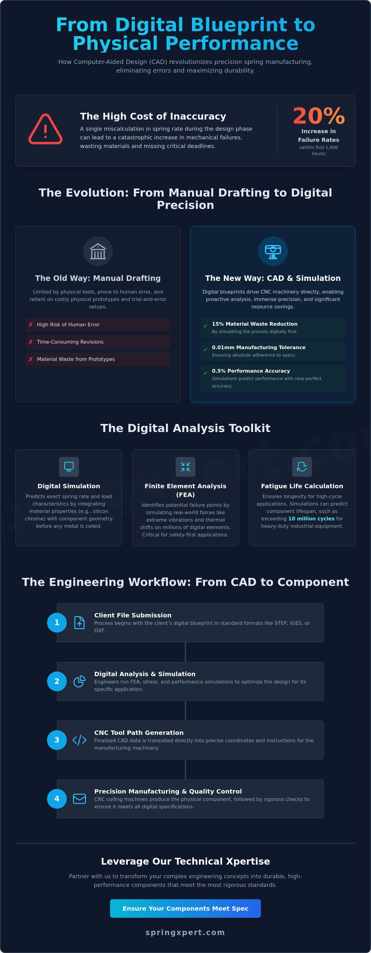
Modern spring production relies on the integration of Computer-Aided Design to translate complex engineering requirements into physical components. Within the UK industrial sector, the transition from manual drafting tables to digital workstations became standard practice by the late 1990s. This shift allowed engineers to move beyond the limitations of ink and paper, facilitating a level of precision that manual methods cannot replicate. In contemporary facilities, computer aided design serves as the foundational data source for CNC (Computer Numerical Control) coiling machinery. The integration between digital blueprints and manufacturing hardware is seamless. When an engineer finishes a design, the software generates coordinates that drive the CNC tool paths. This direct link eliminates the risk of human error during the setup phase. Accuracy is maintained within tolerances as tight as 0.01mm, ensuring that every batch of springs meets rigorous British Standards. By simulating the coiling process digitally, manufacturers identify potential stress points or material interference before a single millimetre of wire is consumed. This proactive approach reduces material waste by approximately 15% compared to traditional trial-and-error setups.Distinguishing 2D Drafting from 3D Modelling
For standard compression, extension, or torsion springs, 2D drafting is often sufficient. These files provide the necessary wire diameter, mean diameter, and pitch specifications required for high-speed production. However, bespoke wire forms and complex assemblies require the depth of 3D modelling. 3D environments allow our specialists to visualize how a spring interacts with surrounding housing or mechanical linkages. We ensure full compatibility by accepting various file formats, including STEP and IGES, which streamlines the transition from client concept to our production floor.The Evolution of Digital Prototyping
Technical Precision: How CAD Simulations Predict Spring Performance
Precision in modern spring engineering begins with data. Integrating specific material properties into computer aided design software eliminates the guesswork traditionally associated with prototyping. Engineers determine the exact spring rate and load characteristics of a component while it exists only as a digital file. This process involves mapping the tensile strength and elastic modulus of specific alloys, such as silicon chrome or phosphor bronze, against the intended geometry. In a typical design office in the UK industrial heartlands, a senior British engineer might use these simulations to ensure a spring performs within a 0.5% tolerance of the required specification.
Predicting performance before the first coil is wound saves both time and material waste. High-cycle industrial applications, such as those found in automotive valve trains or heavy-duty pressing equipment, require absolute certainty regarding stress distribution. If a design shows excessive stress at the inner radius of a coil, the computer aided design model is adjusted instantly. This iterative digital process ensures that the physical component is optimised for its specific working environment before production begins on the factory floor.
Finite Element Analysis (FEA) in Spring Design
Finite Element Analysis is a method for predicting how a spring reacts to real-world forces by breaking the structure down into millions of smaller elements. This simulation is critical for safety-critical components used in UK infrastructure and aerospace. It allows a specialist designer to visualise how a spring behaves under extreme vibrations or thermal shifts. Identifying potential failure points in complex torsion or disc spring designs prevents costly mechanical breakdowns. This level of digital scrutiny is a core part of the modern product development cycle, as detailed in MIT OpenCourseWare on Design and Manufacturing.
Calculating Fatigue Life and Material Stress
Longevity is a non-negotiable requirement in the medical and recycling sectors. Digital tools facilitate the selection of optimal wire diameters and material alloys to meet BS EN 13906 standards. For a recycling plant's sorting equipment, simulations might predict a fatigue life exceeding 10 million cycles under constant impact. In the medical field, where a spring might be part of a life-saving drug delivery device, CAD tools ensure the material stress remains well below the elastic limit to prevent permanent deformation.
By using these advanced digital diagnostics, manufacturers guarantee that every batch of springs meets the rigorous demands of British industry. If you require a component that balances high tensile strength with specific spatial constraints, you should consult with bespoke engineering specialists who can validate your requirements through technical simulation.
Bespoke Spring Design: A Case Study in CAD-Driven Problem Solving
In early 2023, a Sheffield-based manufacturer of high-pressure valve systems approached SpringXpert with a critical engineering bottleneck. The client required a custom compression spring capable of maintaining a consistent 485N load within a restricted 20mm diameter housing. Standard off-the-shelf components were unable to provide the necessary force without exceeding the maximum solid height of 15mm. This required a ground-up approach using computer aided design to navigate the narrow margin between mechanical performance and physical space.
The engineering team initiated an iterative design process to address the high-stress environment. By manipulating the spring index and adjusting the pitch, the team developed a geometry that distributed stress evenly across the active coils. Using computer aided design software, engineers simulated various wire diameters, eventually selecting a 3.2mm chrome silicon alloy for its superior fatigue resistance. The digital environment allowed for the testing of 14 different iterations within a single afternoon, a process that would've taken weeks using traditional physical prototyping.
Collaborative Engineering with UK Clients
The success of bespoke projects relies on the technical consultancy provided during the initial phase. Picture a senior British engineer at a workstation in a West Midlands facility, his focus fixed on a 3D spring model displayed across dual monitors. He isn't just looking at a shape; he's evaluating the interaction between the wire cross-section and the housing wall. This collaborative process ensures that functional requirements, such as operating temperature and corrosive exposure, are translated into precise geometric specifications before a single length of wire is cut.
- Technical reviews of spring rate and initial tension.
- Material selection based on UK industrial standards.
- Direct communication between the client's R&D team and our manufacturing specialists.
From Digital Model to Physical Verification
The transition from a digital blueprint to a precision component is seamless because the CAD file acts as the single source of truth for manufacturing. This digital file directly governs the CNC coiling machines, ensuring that every coil is positioned with micron-level accuracy. In the Sheffield case study, this precision meant the final component met all performance criteria on the very first production run. Quality control measures don't just happen at the end; they're integrated throughout the process.
Our technicians use automated optical measuring systems to compare the physical spring against the digital master in real time. This rigorous verification process ensures that the 485N load requirement was met with a variance of less than 1.5%. By eliminating the need for multiple physical prototypes, the client reduced their development timeline by 22 days and avoided the costs associated with iterative tooling adjustments. The result was a stable, reliable component ready for immediate integration into the client's valve assembly.
The Engineering Workflow: Transitioning from CAD Models to CNC Production
The transition from a digital file to a physical component is a structured technical process. It begins when a client provides technical drawings or 3D files in STP, IGS, or DXF formats. These files serve as the definitive source of truth for the project. SpringXpert engineers perform a comprehensive Design for Manufacturability (DFM) review to identify potential production risks early. We use computer aided design software to run digital simulations of load and stress. This allows us to verify performance specifications before any physical tooling is set up. By simulating the spring's behaviour under 100% of its expected load, we eliminate the need for costly trial-and-error prototypes. Once the simulation is successful, we convert the CAD data into G-code or proprietary machine instructions for our CNC coiling and forming machinery. The workflow concludes with a final inspection where digital measuring equipment, such as automated optical comparators, validates the finished part against the original digital blueprint.
Ensuring Manufacturability in Design
Common errors in the initial design phase, such as unrealistic corner radii or conflicting tolerances, can lead to significant manufacturing delays. Our UK-based technicians review every file to ensure wire forms are optimised for efficient CNC production. They apply their deep understanding of metallurgy to adjust for "spring back" and material fatigue. This human expertise, rooted in the British engineering tradition, ensures that the computer aided design model isn't just a visual representation but a viable manufacturing plan. This proactive approach reduces material scrap rates by an average of 12% across bespoke orders.
Technical Documentation and Traceability
Precision manufacturing requires rigorous record-keeping. We generate accurate Bills of Materials (BOM) directly from the CAD data, ensuring that every alloy grade and wire diameter is documented. Every custom component is fully traceable through the manufacturing chain. We assign unique batch numbers that link back to the original material mill certificates, providing a clear audit trail for quality assurance. This level of detail is standard for all our projects, including our specialised work on custom compression springs. By integrating digital data with physical logistics, we maintain a 99.8% accuracy rate in our technical documentation.
Contact our technical department to discuss your custom project requirements.
Strategic Advantages of CAD-Integrated Manufacturing with SpringXpert
SpringXpert bridges the gap between digital innovation and physical application. We apply over 20 years of technical expertise to every project, ensuring the transition from computer aided design to the factory floor is precise and efficient. Our UK-based manufacturing facility supports national coverage, providing a reliable supply chain for both standard stock items and bespoke custom designs. We focus on the physical reality of spring performance, prioritising industrial durability and strict adherence to specified tolerances.
Our operations are built on a foundation of engineering facts. We don't rely on marketing claims; we rely on the measurable performance of our components. Whether you require a single prototype or a production run of 50,000 units, our facility manages the workload with systematic consistency. This approach ensures that every spring, from a simple compression coil to a complex torsion component, meets the exact requirements defined in your initial digital blueprint. Our commitment to quality is reflected in our rigorous testing protocols, which verify tensile strength and fatigue life before any batch leaves the site.
Partnering with a Technical Specialist
Engineering firms choose SpringXpert because we act as a technical authority within high-performance sectors. Our production facility is a classic UK industrial environment. Here, experienced British white engineers monitor CNC machinery to ensure every alloy maintains its integrity during the forming process. This authentic setting combines modern computer aided design integration with traditional mechanical knowledge. We understand the complexities of B2B requirements, where a minor error in load-bearing calculations can lead to component failure. By keeping all manufacturing within the United Kingdom, we provide our partners with a transparent and stable procurement route that avoids the risks of international shipping delays.
Next Steps for Your Engineering Project
Moving a project forward requires a structured approach to technical validation. You can submit your CAD files for a detailed review by our senior engineering team. We assess the geometry and load-bearing specifications to confirm the design is ready for the manufacturing stage. If you're currently in the development phase, we provide bespoke prototyping services. This allows you to test the physical component in its intended environment before committing to a larger order. Our team is also available to discuss material selection, ensuring the chosen alloy matches your requirements for fatigue life and environmental resistance. Contact us today to begin a technical collaboration on your next precision project.
Advancing Industrial Performance Through Digital Precision
Integrating computer aided design into the spring manufacturing workflow transforms theoretical blueprints into high-performance components with measurable accuracy. This digital approach allows our engineers to simulate stress analysis and material fatigue before any metal is coiled. It eliminates the guesswork often associated with complex spring geometries. It's a process that bridges the gap between virtual modelling and our CNC production lines, ensuring strict adherence to ISO-compliant quality standards at our UK facility.
We offer over 20,000 standard products for immediate dispatch, yet our core strength lies in solving unique mechanical challenges. Our technical consultancy provides detailed insights into material selection and tensile strength requirements to ensure your components perform under specific load conditions. Whether you're developing a prototype or scaling up production, our team applies rigorous engineering principles to every project.
Discuss your bespoke spring design requirements with our engineering team to see how our technical expertise can support your next industrial project. We look forward to working with you.
Frequently Asked Questions
What file formats do you accept for custom spring design?
We accept standard industry formats including STEP, IGES, and DXF for 2D profiles. These files integrate directly with our CNC equipment to ensure 100% geometric fidelity. Our engineering team in the West Midlands facility also works with native SolidWorks and Autodesk Inventor files. Providing these formats eliminates manual data entry errors and accelerates the transition to production for your precision components.
Can you help me design a spring if I only have the load requirements?
Yes, our technical team uses computer aided design to engineer bespoke solutions based solely on your load, deflection, and space constraints. We calculate the required wire diameter, coil count, and material grade, such as BS EN 10270-1 carbon steel, to meet your performance criteria. This process ensures the spring operates within 95% of its elastic limit to prevent premature fatigue failure in heavy-duty industrial applications.
How does CAD help in reducing the cost of bespoke spring manufacturing?
CAD reduces manufacturing costs by identifying design flaws during the digital phase before any physical material is consumed. By using computer aided design, we eliminate the need for multiple physical prototypes, which can cost £500 or more per iteration in tooling and setup time. Virtual stress analysis ensures that 100% of the material selection is optimised for the application, reducing waste and raw material expenses.
Is CAD necessary for simple compression or extension springs?
While simple springs can be manufactured from basic dimensions, CAD provides a digital record that ensures 100% repeatability for future orders. It allows us to generate precise technical drawings that define tolerances according to BS 1726 standards. This documentation is vital for quality control. It ensures that every batch of springs matches the original specification exactly, regardless of when the production run occurs.
Can CAD simulate the environment the spring will operate in?
We utilise Finite Element Analysis (FEA) within our CAD environment to simulate operational stresses and environmental factors. This software predicts how a spring will respond to 1,000,000 cycles or high-temperature conditions exceeding 200°C. By testing these variables digitally, we verify that the chosen alloy will resist corrosion and relaxation in specific UK industrial environments before manufacturing begins. It's a critical step for reliability.
How accurate is the transition from a CAD model to the physical spring?
The transition is highly accurate, with our CNC coiling machines maintaining tolerances as tight as +/- 0.01mm on critical dimensions. We export digital coordinates directly to the production floor, which removes the risk of human error during machine setup. Every finished component undergoes digital measurement against the original CAD model to ensure it meets 100% of the customer's geometric requirements. Accuracy is our primary manufacturing priority.
What is the difference between CAD and CAM in your manufacturing process?
CAD refers to the digital design and engineering of the spring, while CAM involves the software that controls our CNC machinery. The CAD model defines the physical geometry and material properties. The CAM system then converts this data into G-code, which instructs the machine tools on how to form the wire. This integrated workflow ensures that the final product is a precise physical manifestation of the digital blueprint.
Can you provide technical drawings if I don’t have my own CAD software?
Our engineering department provides full technical drawings and 3D models for clients who lack internal design capabilities. We produce detailed PDF blueprints and STEP files that you can integrate into your larger assembly designs. This collaborative approach ensures that the spring interfaces perfectly with your other components. It reduces the risk of assembly interference by 100% during the final build phase in your facility.