

Spring Design for Engineers: A Technical Reference Guide for 2026
A 10% error in load calculation at the design stage frequently leads to a 50% reduction in the operational lifespan of a mechanical assembly. Engineers across the UK's industrial landscape recognize that the gap between a theoretical CAD model and a physical component is often where precision fails. You've likely experienced the frustration of a prototype that meets every digital constraint but fails under real-world stress or environmental extremes.
This technical reference guide for 2026 provides the rigorous data required to master spring design for engineers, ensuring your specifications meet strict lifecycle requirements and performance benchmarks. We've compiled the essential mathematical models and material properties needed to bridge the gap between design and the shop floor. You'll learn how to optimize the performance-to-cost ratio while maintaining the exact tolerances required for modern mechanical systems. This article outlines the transition from initial specification to a seamless manufacturing handoff, leveraging our Xpert identity to ensure your next project is both durable and efficient.
Key Takeaways
- Master the mathematical principles of spring design for engineers, focusing on Hooke’s Law and precise spring rate calculations for multi-stage assemblies.
- Select optimal materials by comparing the tensile strength and environmental resistance of music wire, stainless steels, and specialist alloys.
- Align theoretical CAD models with CNC winding capabilities using BS EN 15800:2009 standards to ensure rigorous tolerance management.
- Streamline the transition from initial concept to component through bespoke technical consultancy and rapid prototyping validation.
- Establish precise spatial envelopes and functional parameters to maximise energy storage and mechanical performance in industrial applications.
Fundamentals of Spring Specification and Initial Parameters
Effective spring design for engineers begins with a rigorous definition of the component's primary mechanical role. Whether the application requires energy storage, shock absorption, or precise force application, the initial parameters dictate the entire manufacturing workflow. Our British engineering teams, operating within ISO-certified UK facilities, analyze these parameters to ensure the final product meets stringent aerospace or automotive standards. Understanding the Fundamentals of spring design is essential before selecting wire diameters or material grades.
The operating environment significantly influences material selection. A spring designed for a vacuum environment or a chemical processing plant in the North Sea requires different alloys than one for a climate-controlled laboratory. For instance, if temperatures exceed 300°C, standard carbon steels fail due to relaxation; Inconel or X750 alloys become necessary. We prioritize data-driven material selection to prevent premature stress corrosion cracking or hydrogen embrittlement in harsh UK industrial settings.
Defining the Design Envelope
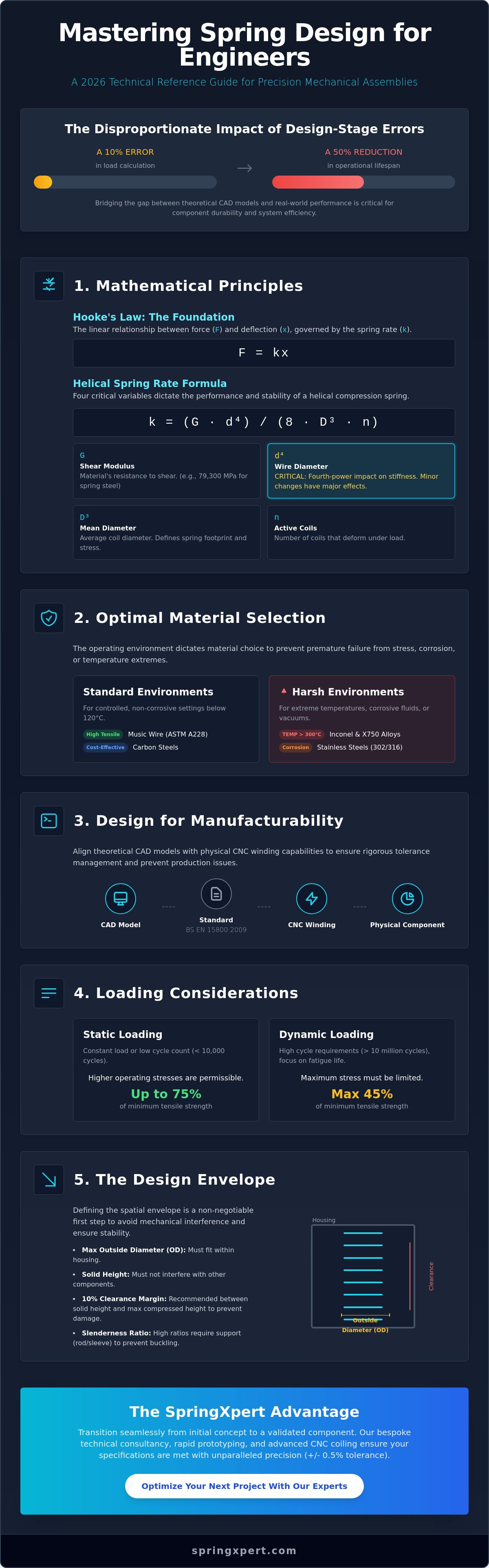
Establishing the spatial envelope is a non-negotiable first step. Engineers must determine the maximum outside diameter (OD) and the solid height to avoid interference with housing walls or internal components. When calculating available space versus required travel, it's vital to maintain a safety margin. We typically recommend a minimum of 10% clearance between the solid height and the maximum compressed height to prevent mechanical damage. The relationship between hole and rod diameters is equally critical; a spring with a high slenderness ratio will buckle if not properly supported by an internal rod or external sleeve. Specifying ground ends ensures a more uniform load distribution, reducing the risk of eccentric loading that can lead to lateral instability.
Static vs. Dynamic Loading Considerations
Distinguishing between static and dynamic applications changes the safety factors used in spring design for engineers. Static applications, where the load is constant or applied fewer than 10,000 times, allow for higher operating stresses closer to the material's elastic limit. Dynamic applications require a focus on fatigue life. For high-cycle requirements, such as 10 million cycles in an automotive valve train, we limit the maximum stress to 45% of the minimum tensile strength. Extension springs introduce the additional variable of initial tension; this is the internal force that holds the coils together. Precise control of this tension is necessary for consistent performance in tension-critical assemblies. Our Xpert team utilizes advanced CNC coiling technology to maintain these tolerances within +/- 0.5% of the specified load. We invite technical collaboration at the earliest design stage to optimize these custom-engineered solutions for your specific UK manufacturing requirements.
Mathematical Principles: Formulas for Precision Engineering
Hooke’s Law, defined by the formula F = kx, serves as the primary foundation for spring design for engineers. While the linear relationship between force and deflection is straightforward in isolation, it becomes more complex in multi-stage assemblies. In these systems, engineers must calculate equivalent spring rates for series or parallel configurations to manage varying load requirements. For instance, a series arrangement reduces the overall rate, while a parallel setup increases it, allowing for precise control over the mechanical response in high-precision UK automotive components. This mathematical grounding ensures that every component performs exactly as specified in the technical drawings.
The Essential Spring Rate Formulas
Calculating the spring rate (k) for a helical compression spring requires four critical variables. The formula k = (G * d^4) / (8 * D^3 * n) demonstrates how specific physical properties dictate performance. Our British engineering teams utilize these variables to ensure stability in industrial applications:
- Shear Modulus (G): This represents the material's resistance to shearing strain, typically around 79,300 MPa for standard spring steel.
- Wire Diameter (d): The thickness of the wire, which has a fourth-power impact on the spring rate.
- Mean Diameter (D): The average of the inner and outer coil diameters, determining the spring's physical footprint.
- Active Coils (n): The number of coils that actually deform under load; reducing this count increases the rate.
Adjusting the active coil count provides a reliable method for fine-tuning the rate during the prototyping phase. We integrate these formulas into system-wide mechanical simulations to ensure the spring interacts correctly with other moving parts before manufacturing begins.
Stress Analysis and Fatigue Life
Static load calculations don't account for the stress concentrations that occur on the inner diameter of a coil. To address this, engineers apply the Wahl correction factor to compensate for curvature and direct shear. For high-cycle industrial applications, such as those found in UK power generation plants, determining the safety factor is vital for preventing catastrophic failure. We utilize Shigley's Mechanical Engineering Design as a reference standard for calculating these stresses. By using Goodman diagrams, we can predict spring longevity under fluctuating loads, ensuring the alloy's endurance limit isn't exceeded during its 10 million cycle lifespan.
Efficiency in potential energy storage is another key metric for spring design for engineers. The energy (U) stored is calculated as U = 0.5 * k * x^2. In rapid-release mechanisms, the efficiency of this energy transfer depends on the material's damping characteristics and the precision of the coil geometry. If you're developing a complex mechanism, you can consult with our technical specialists to optimize these mathematical variables for your specific application.
Material Selection: Performance, Environment, and Longevity
Effective spring design for engineers begins with a rigorous assessment of the operating environment. Carbon steels like Music Wire (ASTM A228) provide the highest tensile strength and fatigue life for dry, non-corrosive settings. However, when exposure to moisture or chemicals is a factor, stainless steels become the baseline. Grade 302 offers a balance of strength and corrosion resistance, while Grade 316 is preferred for marine environments due to its molybdenum content. For high-stress applications requiring the properties of both, 17-7 PH stainless steel delivers superior fatigue resistance through precipitation hardening.
When temperatures exceed 300°C or environments involve high acidity, specialist alloys are necessary. Inconel 718 and X750 maintain their mechanical integrity at temperatures up to 700°C. Monel 400 provides exceptional resistance to hydrofluoric acid and seawater. Titanium alloys offer a 40% weight reduction compared to steel, making them critical for UK aerospace components where mass efficiency is vital. Our UK-based technicians frequently specify these materials to ensure long-term reliability in North Sea oil and gas operations.
The 2026 UK environmental standards place stricter limits on material sourcing and the use of hazardous substances in coatings. Engineers must now account for the phase-out of certain traditional plating chemicals. This shift focuses heavily on trivalent chromium and zinc-nickel finishes that meet updated REACH compliance. Selecting the wrong material or coating doesn't just risk mechanical failure; it risks non-compliance with these evolving British industrial regulations.
Standard vs. High-Performance Alloys
Specifying the right alloy involves balancing cost against failure risk. Chrome Silicon (ASTM A401) is the industry standard for high-temperature valve springs and die applications because it resists relaxation better than standard carbon steel. In medical and aerospace sectors, we ensure 100% material traceability. This includes mill test reports and chemical analysis to verify that the alloy meets the precise specifications required for life-critical systems. Using 17-7 PH in these high-stress environments ensures the component doesn't succumb to fatigue under cyclic loading.
Surface Treatments and Protective Coatings
Surface integrity is as important as the base metal in professional spring design for engineers. Zinc plating provides sacrificial protection but carries a risk of hydrogen embrittlement if not baked correctly after processing. Passivating stainless steel removes surface iron to enhance the natural oxide layer without the embrittlement risk. Shot peening remains the most effective mechanical treatment. It increases fatigue life by up to 50% by introducing compressive residual stresses on the spring surface. For electrical insulation or visual identification, powder coating and plastic dipping provide durable, high-visibility finishes that withstand harsh handling on the factory floor.
Design for Manufacturability (DfM) and Tolerance Management
Effective spring design for engineers requires a transition from idealised CAD environments to the physical constraints of CNC multi-axis coiling machines. While a digital model assumes perfect uniformity, real-world production must account for the 3% to 5% variation in wire tensile strength often found within a single batch of material. Adhering to BS EN 15800:2009 provides a standardised framework for cold-coiled springs, defining Grade 1 (precision), Grade 2 (standard), and Grade 3 (wide) tolerances. Selecting Grade 1 for non-essential dimensions can increase production costs by 25% or more due to higher scrap rates and slower machine cycles. The Xpert approach involves balancing these tolerances to ensure functional performance without inflating the unit price.
Optimising Tolerances for Production
Engineers should distinguish between mandatory and reference dimensions on technical drawings. Mandatory dimensions, such as spring rate or loaded length, dictate the primary performance. Reference dimensions like total coils or free length allow the manufacturer to adjust for material variance during the run. Material choice directly impacts achievable tolerances. For instance, high-tensile alloys like 17-7 PH stainless steel exhibit different spring-back characteristics compared to standard carbon steels. Specifying a +/- 1.5% tolerance on a coil diameter is achievable but requires constant monitoring by UK-based technicians using automated laser gauging during the winding process. Using standard tolerances where precision isn't critical keeps the project within budget.
Reducing Manufacturing Friction
Bespoke wire forms often fail during production when designers specify "impossible" geometries, such as internal radii smaller than the wire diameter. This causes stress concentrations and tool interference. End-grinding is another critical factor; it improves squareness and load parallelism but introduces heat that may require secondary stress-relieving. Planning for secondary operations like heat treatment at 250°C to 450°C or shot peening is essential to ensure the final component meets the fatigue life requirements established in the initial spring design for engineers. These processes often cause minor dimensional shifts that must be calculated during the initial coiling setup. Our technicians monitor these shifts to ensure the final product remains within the specified envelope.
To ensure your specifications align with current CNC capabilities, consult with a SpringXpert engineer for a full DfM review.
The Bespoke Engineering Process: From CAD to Component
Engineers often encounter performance ceilings when using off-the-shelf components for specialised applications. While SpringXpert maintains a comprehensive inventory of 20,000+ standard stock items, complex mechanical systems frequently require a more tailored approach. Professional spring design for engineers transitions from standard catalogues to bespoke manufacturing when specific tensile strengths, unique alloys, or tight spatial tolerances are non-negotiable. This process relies on technical consultancy to bridge the gap between a conceptual CAD model and a functional industrial component that survives millions of cycles.
Collaborative Design and Prototyping
The journey to a custom solution starts with the submission of technical data. We accept CAD files in STEP, IGES, or DXF formats to conduct a thorough analysis of the spring's geometry within its intended housing. This stage allows our UK-based engineering team to identify potential stress points or interference issues before any metal is formed. We recommend low-volume production runs, typically ranging from 10 to 50 units, for rigorous field testing. This iterative design phase uses physical prototype data to refine wire diameters or coil pitches. It's a vital step that ensures the final product meets the exact load requirements of your assembly under real-world conditions.
Final Specification and Batch Production
After successful validation, we finalise the technical drawing for national-scale procurement. This document defines the exact material grade, such as 17-7 PH stainless steel or Chrome Vanadium, and sets the permissible tolerances for the production run. Lead times for custom components generally fall between 15 and 25 working days, a timeline that reflects the precision required for bespoke tooling and heat treatment. Every batch produced in our UK facilities undergoes strict quality control to ensure reliability. Our specialists, who represent the backbone of the British manufacturing sector, perform several critical checks:
- Digital load testing to verify spring rates against theoretical models.
- Dimensional inspection using high-precision callipers and optical comparators.
- Material certification to ensure full traceability and compliance with BS EN standards.
- Fatigue testing for components destined for high-cycle environments.
Precise spring design for engineers doesn't end at the drawing board; it concludes with a component that's built for durability and consistency. Our team of time-served specialists ensures that every custom-engineered part aligns with ISO 9001 quality management systems. Partner with the Xperts for your next project. Consult our engineering team today.
Achieving Precision in Mechanical Performance
Effective spring design for engineers requires a meticulous balance of mathematical accuracy and material science. Success in 2026 relies on managing tolerances within ISO-aligned quality standards while selecting alloys that withstand specific environmental stressors. We've established that integrating Design for Manufacturability (DfM) during the initial CAD phase reduces lead times and prevents component failure in high-stress applications. These technical foundations ensure that every coil meets the required tensile strength and fatigue life targets specified in your project brief.
SpringXpert brings over 20 years of technical engineering expertise to every project. Our facility maintains an inventory of 20,000+ standard products and provides full material traceability for all custom components. Whether you're operating within the UK automotive sector or precision aerospace manufacturing, we provide the stability and industrial reliability your specifications demand. Our team bridges the gap between complex theoretical formulas and tangible industrial hardware. We're ready to apply our systematic approach to your unique requirements.
Explore our Bespoke Spring Design and Prototyping Services
We look forward to partnering with your engineering team to solve your next mechanical challenge with absolute precision.
Frequently Asked Questions
What is the most common mistake engineers make in spring design?
The most common mistake in spring design for engineers is failing to account for sufficient solid height clearance, which should ideally represent 10% of the total deflection. Many designers specify a total travel that forces the spring to its physical limit, causing immediate mechanical failure or permanent set. At our UK facility, we observe that 15% of initial designs require adjustment to avoid this specific coil clash.
How do I determine if I need a custom spring or a standard stock component?
You need a custom spring when standard components fail to meet exact load requirements within a 5% margin or when spatial constraints are non-standard. Stock springs often require compromises in longevity or performance. If your application involves dynamic loading over 100,000 cycles, a bespoke solution ensures the material grade and pitch are optimized for your specific stress profile and fatigue requirements.
What are the standard manufacturing tolerances for UK industrial springs?
Standard manufacturing tolerances for UK industrial springs are defined by BS EN 15800:2008 for compression springs, categorized into Grades 1, 2, and 3. Grade 2 is the industry standard for most mechanical applications. For example, a wire diameter of 2.00mm under Grade 2 allows a tolerance of plus or minus 0.03mm. Precision aerospace components often require Grade 1 to ensure tighter assembly fits.
How does temperature affect the performance and rate of a spring?
High temperatures reduce the modulus of rigidity of the spring material, which directly lowers the spring rate. For standard carbon steel, performance begins to degrade significantly once temperatures exceed 120°C. If your operating environment reaches 250°C, you must specify alloys like Inconel X750. These materials maintain their elastic properties where standard music wire would suffer from rapid relaxation and significant load loss.
What is the Wahl correction factor and why is it critical for safety?
The Wahl correction factor is a mathematical constant used to calculate the maximum shear stress on the inner radius of a coil. It accounts for the curvature of the wire and the stress concentration that occurs during compression. Neglecting this factor can lead to an underestimation of stress by up to 30% in springs with a low index. This calculation is vital for safety-critical components.
Can I use a compression spring as an extension spring in a design?
You can't use a compression spring as an extension spring because the end geometries and internal stresses are fundamentally different. Compression springs are designed to resist axial force through shortening, while extension springs require loops or hooks to pull loads. Attempting to reverse their function leads to immediate structural failure. Our engineers recommend using a drawbar spring assembly if you require extension behavior with compression safety.
What information is required for a bespoke spring design quote?
To provide an accurate bespoke spring design quote, we require the wire diameter, outside diameter, free length, and total number of coils. You should also specify the material grade, such as 302 stainless steel or BS 5216 carbon steel. Providing the required load at a specific compressed length allows our technical team to verify the spring rate and ensures the design meets your 2026 project specifications.
How do I calculate the fatigue life of a spring under dynamic load?
Calculate the fatigue life by plotting the minimum and maximum operating stresses on a Goodman Diagram. For high-cycle applications, the stress range must remain below the endurance limit of the material, typically 45% of the minimum tensile strength for carbon steels. Shot peening the surface can increase fatigue life by 200% or more by introducing beneficial compressive residual stresses that resist crack propagation.