

Common Causes of Spring Failure: An Engineering Guide to Prevention
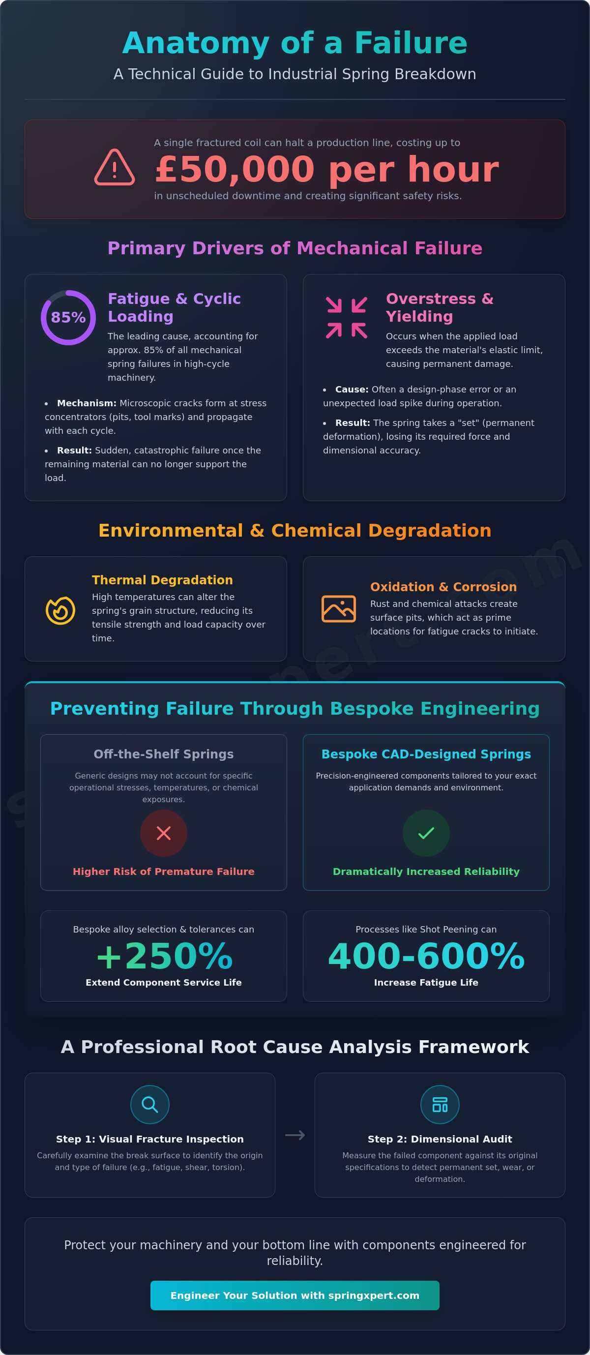
A single fractured coil can halt a £50,000-per-hour production line in a matter of milliseconds. You know that mechanical reliability is the foundation of any UK manufacturing facility, yet unexpected component fatigue remains a constant threat to your operational efficiency. Identifying the common causes of spring failure is the first step toward eliminating unscheduled downtime and the safety risks associated with catastrophic part breakdown. Whether it's a high-tensile compression spring or a complex torsion component, the physical realities of the application dictate the longevity of the system.
This guide provides a technical analysis of why springs fail and how precision engineering can mitigate these risks. Our Xpert engineering team outlines how specific alloy selections and tight manufacturing tolerances can extend the service life of a component by more than 250% in high-cycle environments. We'll examine the physics of stress concentration, the role of hydrogen embrittlement, and a structured framework for specifying bespoke springs that meet the rigorous demands of modern British industry. By the end of this technical briefing, you'll have the data required to make informed specification decisions that protect your machinery and your bottom line.
Key Takeaways
- Identify how cyclic loading and exceeding material yield strength serve as the most common causes of spring failure in heavy industrial machinery.
- Evaluate the critical role of environmental factors, such as thermal degradation and oxidation, in reducing effective wire diameter and tensile strength.
- Implement a professional root cause analysis framework using visual fracture inspections and dimensional audits to diagnose mechanical defects accurately.
- Understand why bespoke CAD-designed components outperform off-the-shelf springs in specialized UK industrial environments.
Understanding the Mechanical Stakes of Industrial Spring Failure
In the context of British industrial engineering, the distinction between expected component wear and premature mechanical failure is a critical boundary for operational safety. A senior engineer at a precision manufacturing plant in the West Midlands doesn't view a fractured spring as a mere maintenance task. Instead, it's a data point indicating a breakdown in the system's design or environmental assumptions. Identifying the common causes of spring failure requires a meticulous approach to metallurgy and load dynamics. When a component fails before its calculated fatigue life, the consequences ripple through the entire production chain.
The economic impact of these failures is substantial. Data from UK manufacturing sectors suggest that unplanned downtime can cost a facility between £10,000 and £25,000 per hour depending on the complexity of the assembly line. Beyond the immediate loss of productivity, a sudden break often leads to secondary equipment damage. In heavy recycling facilities or construction environments, a failed tension spring can release stored energy violently, risking the safety of the site's workforce. The engineer's role is to act as a technical gatekeeper, using diagnostic tools to spot microscopic stress fractures or dimensional shifts before a catastrophic event occurs.
Reliability depends on a deep understanding of spring mechanics and materials. Every alloy has a specific limit where it transitions from elastic performance to permanent deformation. If an engineer misses the signs of this transition, they aren't just risking a part; they're risking the integrity of the entire machine. Precision and stability are the foundations of a dependable industrial partnership.
Defining Spring Failure in Engineering Terms
Failure isn't always a clean break. In technical terms, it's any deviation from specified load requirements or dimensional tolerances that prevents a machine from functioning correctly. This often manifests as a transition from elastic deformation to a permanent plastic set. "Near-miss" failures, such as a spring losing 4% of its required rate, are frequently more dangerous than immediate breaks. They cause subtle timing issues and increased friction that degrade other expensive components over time.
The Life Cycle of a High-Performance Spring
Establishing a baseline for fatigue life begins in the design phase. Engineers must define the working environment, including temperature ranges and corrosive exposures typical of UK industrial sites, before production starts. It's essential to recognize that compression springs handle energy storage through axial pressure, which creates different internal shear stresses than those found in extension or torsion types. Analyzing the common causes of spring failure during the design cycle ensures that the chosen alloy and wire diameter can withstand the projected millions of cycles required for high-performance applications.
The Primary Drivers of Mechanical Spring Failure
Identifying the common causes of spring failure requires a rigorous analysis of the operating environment. Most mechanical failures aren't random events. They result from predictable stressors or chemical interactions that compromise the alloy's integrity. In high-performance UK industrial applications, understanding these drivers is the first step toward effective prevention.
Fatigue and Cyclic Loading Mechanisms
Fatigue accounts for approximately 85% of mechanical spring failures in high-cycle machinery. Engineers rely on the S-N curve, which plots stress against the number of cycles, to determine the fatigue life of a component. When a spring operates near its endurance limit, microscopic cracks begin to form. These cracks usually start at surface imperfections like pits or tool marks, which act as stress concentrators. These small defects eventually propagate through the cross-section of the wire until the remaining material can't support the load. Shot peening is a critical process for extending service life. By bombarding the surface with spherical shot, we create a layer of compressive residual stress. This process can increase the fatigue life of a standard compression spring by 400% to 600%.
Stress Calculations and Yield Strength
Overstressing is a frequent design-phase error. It happens when the applied load forces the material beyond its yield strength, leading to permanent deformation or "set." Many design failures occur because the engineer didn't account for the Wahl correction factor, which calculates the increased stress on the inner diameter of the coil. The relationship between wire diameter, coil count, and mean diameter is precise. A 10% reduction in wire diameter can result in a 35% decrease in load capacity. While Hooke’s Law (F=kx) provides a baseline for linear rate verification, it doesn't reveal if the spring is operating within its safe elastic limits. Utilizing bespoke engineering services ensures that every dimension is validated against the specific tensile strength of the chosen alloy.
Hydrogen embrittlement is a hidden danger that specifically targets high-tensile steel springs. It's most common in materials with a tensile strength exceeding 1450 MPa that have undergone acid pickling or electroplating. Hydrogen atoms migrate into the grain boundaries of the metal, making it brittle and prone to sudden cracking under static loads. Impact loading is another critical factor. This occurs when a spring is hit with sudden kinetic energy rather than a controlled, gradual force. If the impact velocity exceeds the natural frequency of the spring, it creates a surge wave. This wave causes individual coils to clash, which generates stress levels significantly higher than the calculated maximum for the application.
Environmental and Chemical Factors in Component Degradation
Environmental exposure accounts for roughly 25% of the common causes of spring failure identified in British manufacturing facilities. Oxidation is a primary mechanism where material loss directly reduces the effective wire diameter. Because the load-carrying capacity of a spring is proportional to the wire diameter to the fourth power, a 5% reduction in thickness leads to a 19% loss in spring rate. This degradation often triggers Stress Corrosion Cracking (SCC). This process occurs when tensile stress and a corrosive medium act simultaneously, creating brittle fractures at stress levels significantly lower than the material's rated yield strength. In many UK chemical processing plants, even trace amounts of hydrogen sulphide or chlorides can cause rapid intergranular cracking in non-resistant alloys.
Corrosion and Material Selection
Selecting the correct alloy is the first line of defence against chemical degradation. High-carbon steels provide excellent tensile strength but require robust protection in damp environments to prevent pitting. Zinc plating offers sacrificial protection, while powder coating provides a physical barrier against salt spray. For aggressive chemical exposure, engineers specify 316 stainless steel, which contains 2% to 3% molybdenum to enhance resistance to chloride pitting. Technical data shows that disc springs are particularly effective in submerged industrial applications. Their compact geometry allows for uniform passivation treatments, ensuring the protective chromium oxide layer remains intact even in high-salinity fluids or acidic environments common in North Sea offshore equipment.
Temperature Extremes and Material Relaxation
Thermal degradation manifests as "creep" or material relaxation, which is another of the common causes of spring failure in high-output machinery. When operating temperatures exceed 121°C for standard music wire or carbon steels, the material loses its elastic memory. The spring won't return to its original free length, resulting in a permanent load loss that compromises the assembly's mechanical integrity. Conversely, cryogenic applications reaching -196°C demand austenitic stainless steels to prevent low-temperature embrittlement. At these extremes, the metal becomes brittle and can shatter under standard working loads. Specialist British engineers adjust load calculations by incorporating the temperature coefficient of the shear modulus (G). This ensures the component maintains its specified force throughout its thermal cycle, preventing the catastrophic loss of tension that leads to system downtime.
SpringXpert's technical team works directly with UK-based floor managers and design engineers to audit environmental risks. By matching alloy chemistry to the specific industrial solvents or thermal ranges of your facility, we eliminate the variables that lead to premature component fatigue. Our focus remains on providing precision-engineered solutions that withstand the rigours of the modern British industrial landscape.
A Root Cause Analysis Framework for Spring Failure
Diagnosing why a component failed requires a systematic engineering approach. Our team at SpringXpert utilizes a five-step framework to isolate the specific common causes of spring failure within UK industrial applications. This process ensures that we don't just replace a broken part, but instead optimize the entire system for longevity.
- Step 1: Visual inspection. We examine the fracture surface under 10x to 50x magnification. Technicians look for the crack initiation point, which often reveals whether the failure started at a surface defect or an internal inclusion.
- Step 2: Dimensional audit. We measure the free length, wire diameter, and coil pitch. A reduction of more than 2% in free length indicates the spring has taken a permanent set, suggesting the material exceeded its elastic limit during operation.
- Step 3: Specification review. We compare the original CAD design against the actual operating environment. If a spring designed for a 15% maximum deflection is consistently compressed to 25%, fatigue is inevitable.
- Step 4: Metallurgical analysis. This involves cross-sectional etching to identify decarburization or grain structure irregularities. In our Midlands-based laboratory, our specialists check if the alloy meets the tensile strength requirements specified in BS EN 10270 standards.
- Step 5: System assessment. We evaluate the mating components. Worn guides or misaligned seats often introduce lateral loads that the spring wasn't engineered to withstand.
Interpreting Fracture Patterns
A brittle fracture surface appears flat and granular. This often points to hydrogen embrittlement or excessive hardness from a flawed heat treatment process. Conversely, ductile failures show "necking" or a fibrous texture, signaling a single overstress event. Fatigue failures are identified by "beach marks." These concentric ridges represent the slow progression of a crack over thousands of cycles, accounting for a high percentage of common causes of spring failure. Distinguishing these from manufacturing tool marks is critical; a scratch just 0.05mm deep can act as a stress riser, reducing service life by 40%.
Evaluating Mating Components
Springs don't operate in isolation. Poor alignment leads to lateral buckling, which causes coils to rub against housing walls and generate localized heat. For extension springs, worn anchor points or misaligned hooks lead to premature fracture at the transition radius. We also check for resonance. If the operating frequency of the machinery matches the spring's natural frequency, the resulting harmonic surge can cause failure within minutes. UK facilities using high-speed reciprocating equipment should verify these harmonics during the initial design phase.
Eliminate recurring downtime by identifying the true source of your component issues. Consult with a SpringXpert engineer to receive a technical evaluation of your assembly.
Preventing Failure Through Bespoke Engineering
Standard components are built for average conditions, which makes them a liability in high-stakes industrial environments. Generic springs often fail because they don't account for the specific harmonics or thermal fluctuations of a unique machine. These mismatched specifications are among the most common causes of spring failure in UK production lines. SpringXpert eliminates this risk through a CAD-driven design phase. Our engineers, based in our UK facility, create digital twins to simulate stress distribution. This allows us to refine the geometry and eliminate potential failure modes before manufacturing begins.
The Advantages of Bespoke Specification
Custom specification allows for the precise calibration of tensile strength against specific load profiles. We don't settle for "close enough" measurements. We adjust wire diameters and pitch to manage energy storage, preventing the plastic deformation that ruins component timing. Choosing specialized alloys like Inconel 718 or Chrome Silicon allows for operation in environments that would destroy standard carbon steel. We also tailor end types, such as closed and ground ends, to ensure 360-degree contact. This even distribution of force prevents the localized stress concentrations that lead to sudden fractures at attachment points.
Quality Control and Manufacturing Precision
Our manufacturing floor utilizes multi-axis CNC technology to ensure identical coil geometry across every unit. We maintain tolerances as tight as +/- 0.01mm, which is essential for components integrated into precision aerospace or medical assemblies. Every project starts with rigorous material verification. We test incoming wire batches for grain structure and tensile consistency to ensure the raw material matches the design intent. Our team of experienced British engineers and technicians oversees every stage of production within our UK-based facility, ensuring that traditional craftsmanship and modern automation work in tandem.
In-house testing protocols at SpringXpert include load-deflection testing and high-cycle fatigue simulation. We can subject a bespoke spring to 10 million cycles within a controlled test environment to prove its durability. This data-driven validation ensures that the final product will withstand years of service without losing its elastic properties. Collaborating with our team of technical specialists provides your business with a reliable engineering partner. We focus on the physical reality of performance, delivering springs that maintain their integrity under the most demanding industrial loads.
Optimising Component Longevity through Precision Engineering
Addressing the common causes of spring failure requires a dual focus on material integrity and the specific operational environment. Identifying factors like hydrogen embrittlement or fatigue stress during the initial design stage prevents catastrophic mechanical breakdown and costly industrial downtime. Precision in alloy selection and specialised surface finishing ensures components withstand the rigorous conditions found across the UK manufacturing sector. Our approach prioritises the physical reality of tensile strength and cycle requirements to ensure long term stability.
SpringXpert integrates over 20 years of industrial engineering experience into every bespoke project. Our facility utilises in-house CAD design and rapid prototyping to validate performance before full scale production begins. Because we operate under ISO aligned quality management systems, every spring meets strict dimensional tolerances and safety standards. This technical depth allows us to serve as a reliable partner for complex B2B requirements. Consult with our engineering team for a bespoke spring solution to enhance your system's durability. We're ready to apply our technical expertise to your next mechanical challenge.
Frequently Asked Questions
What are the most common signs that a spring is about to fail?
Visible deformation and surface micro-cracks are the primary indicators that a spring is approaching the end of its service life. If a compression spring loses 5% of its original free length, it's reached its elastic limit and underwent permanent set. Maintenance teams in UK manufacturing facilities shouldn't ignore 0.1mm surface pits. These serve as stress concentrators that lead to sudden fractures during standard operation.
Can a spring fail even if it is not overloaded?
Springs frequently fail below their rated load capacity due to environmental factors or cyclic stress. Fatigue accounts for 80% of mechanical failures in dynamic applications even if the spring's load stays within designed limits. Corrosion also reduces the effective wire diameter. This increases the actual stress on the remaining material beyond safe tolerances, causing an unexpected break despite the absence of an overload.
How does hydrogen embrittlement cause sudden spring failure?
Hydrogen embrittlement causes sudden, brittle failure when atomic hydrogen diffuses into high-strength steel during the electroplating process. This phenomenon typically affects springs with a Rockwell C hardness above 40 HRC. The trapped hydrogen creates internal pressure that triggers fractures within 24 hours of the first load application. We prevent this by baking components at 190°C for 4 hours immediately after they're plated.
What is the difference between fatigue failure and static failure?
Fatigue failure results from repeated loading cycles, while static failure occurs when a single load exceeds the material's ultimate tensile strength. Fatigue is one of the common causes of spring failure in high-speed machinery. It often manifests as a clean break perpendicular to the wire axis. Static failure usually results in visible deformation or "necking" before the material finally yields under excessive force.
How can I calculate the expected lifespan of an industrial spring?
Engineers calculate spring lifespan using the Goodman Diagram to compare mean stress against alternating stress. For carbon steel springs, we design for a 10 million cycle threshold to achieve infinite life under standard conditions. Our Xpert team utilizes specific S-N curves and Wahl factor corrections to predict the exact point where cumulative damage leads to structural compromise. Accurate calculations require precise data on operating temperatures and stroke frequency.
Does the finish of a spring affect its failure rate?
The surface finish directly influences failure rates by either protecting against oxidation or introducing manufacturing defects. A rough surface with a Ra value exceeding 0.8 micrometers increases the likelihood of crack initiation. Conversely, a zinc-flake coating applied per ISO 10683 provides 1,000 hours of salt spray resistance. This finish protects the alloy without the risks associated with acid pickling or traditional electroplating methods.
What should I do if my springs are failing prematurely in a corrosive environment?
You should upgrade to corrosion-resistant alloys like 316 Stainless Steel or Inconel 718 if your springs show signs of rust or pitting. These materials contain 16% to 18% chromium, which forms a protective oxide layer. If environmental conditions include high humidity, our UK-based engineering team recommends applying a thermal diffusion coating. This ensures the spring maintains its 100% load-bearing capacity throughout its intended service life.
Why is shot peening recommended for springs with high cycle counts?
Shot peening is recommended because it creates a layer of compressive residual stress on the wire surface. This process involves bombarding the spring with spherical steel shot at velocities of 60 meters per second. This treatment effectively offsets tensile stresses that cause cracks to grow. Shot peening can increase the fatigue life of a heavy-duty spring by 400% in high-cycle industrial applications where durability is vital.