

Pressed Metal Component Design Tips: 7 Key Rules
Table of Contents
- Understand Sheet Metal Design Rules for Pressed Components
- Select Material and Sheet Thickness Correctly
- Apply Proper Sheet Metal Bend Radius and Bend Allowance
- Position Sheet Metal Holes and Slots for Manufacturability
- Design Flanges, Tabs, and Reliefs to Prevent Cracking
- Set Realistic Pressed Metal Tolerances and Dimensioning
- Plan for Press-Specific Tooling and Die Design
- Validate Design and Prototype Before Full Production
- Frequently Asked Questions
Last Updated: October 16, 2026
Understand Sheet Metal Design Rules for Pressed Components
Pressed metal component design starts with the rules that separate successful parts from costly failures. A pressed metal component is a sheet metal part formed through stamping or pressing, where dies shape the material under high force. These components are everywhere: automotive brackets, electrical enclosures, appliance panels, and subsea equipment housings.
The core challenge: sheet metal doesn't behave like solid material. It flows, springs back, cracks at corners, and resists bending unpredictably. Get the design wrong and you face scrap, rework, tooling delays, and field failures. At SpringXpert, we work with design teams across industrial sectors to catch these issues early.
The difference between a manufacturable design and one destined for the scrap bin comes down to three things: understanding material behaviour, respecting tooling constraints, and validating assumptions early.
Here's what separates good pressed metal component design from the rest:
- Material choice determines what's physically possible
- Bend radius and thickness ratios control cracking risk
- Feature placement relative to bends affects both formability and cost
- Tolerances must match press capability, not wishful thinking
- Tooling design directly influences part quality and cycle time
Select Material and Sheet Thickness Correctly
Material selection is where many designs fail before they reach the press. The wrong choice locks you into problems no amount of clever tooling can solve.
Common materials include mild steel (cost-effective, easy to form), stainless steel (corrosion resistant but harder to work), and aluminium (lightweight, good formability). Mild steel forgives generous bend radii. Stainless steel demands tighter control. Aluminium springs back more aggressively.
Sheet thickness drives manufacturability more than most designers realise. Thicker material requires more tonnage, larger dies, and longer cycle times. Thinner material is cheaper per unit but demands tighter tolerances. A practical rule: select the thinnest gauge that meets strength requirements, then add 0.5mm if you're uncertain about formability. This buffer prevents prototype failures and tooling rework.
Consider these factors when choosing thickness:
- Structural load requirements (bending stress, impact resistance)
- Production volume (higher volumes justify thinner gauges with custom tooling)
- Corrosion environment (thicker material for subsea or chemical exposure)
- Aesthetic requirements (visible surface finish quality)
- Joining method (welding, riveting, or fastener holes affect minimum thickness)
Material grain direction matters too. Rolling direction affects how metal flows during forming. Align critical bends perpendicular to the grain to reduce cracking risk.
Apply Proper Sheet Metal Bend Radius and Bend Allowance
Bend radius is where theory and reality diverge most sharply. Designers often specify radii that look reasonable on paper but fail in the press.
The sheet metal bend radius is the inside radius of a bend. Too tight and the material cracks or tears. Too generous and you waste material and add weight.
A practical starting point: minimum bend radius should be at least equal to material thickness. For mild steel, this often works. For stainless steel, add 50 per cent.
Bend allowance is the actual length of material consumed in the bend, not simply the arc length.
Most CAD software includes bend allowance calculators, but they're only as good as the input data.
Here's a practical approach to bend design:
- Start with manufacturer recommendations for your material and thickness
- Add 10 per cent safety margin to minimum bend radius for production parts
- Build a test sample with your chosen radius before committing to tooling
- Measure the actual bend allowance on the sample and adjust CAD models
- Document the bend radius and allowance for each bend in your design specifications
Springback, the elastic recovery after forming, is the hidden cost. Material springs back slightly after the press releases pressure. Tighter bends spring back more.
Position Sheet Metal Holes and Slots for Manufacturability
Hole placement relative to bends costs thousands when wrong. A hole too close to a bend can distort during forming, creating scrap.
The rule: maintain minimum distance from any hole or slot edge to a bend line. For most materials, this should be at least three times the material thickness, a 1.5mm thick part needs 4.5mm clearance.
Holes in flanges demand more care. A hole near a flange edge can cause tearing during forming. Position holes at least 6mm from any flange edge, or better yet, 10mm.
Slot orientation matters. Slots aligned with the bend direction (parallel to the bend line) are safer than slots perpendicular to it. The material flows differently depending on slot orientation.
Consider these placement guidelines:
- Minimum 3× material thickness from hole edge to nearest bend
- Minimum 6-10mm from hole edge to flange edge
- Avoid clustering holes near bends or corners
- Position critical holes on flat surfaces, not near formed features
- Leave adequate material between slots and bend lines
Pilot holes for fasteners should be slightly oversized to allow for tolerance stack-up. A 6mm hole for a 5mm fastener gives breathing room; a 5.1mm hole guarantees assembly headaches.
Design Flanges, Tabs, and Reliefs to Prevent Cracking
Flanges are the most stressed areas of any pressed component, where material is forced to change direction sharply. Cracks start here.
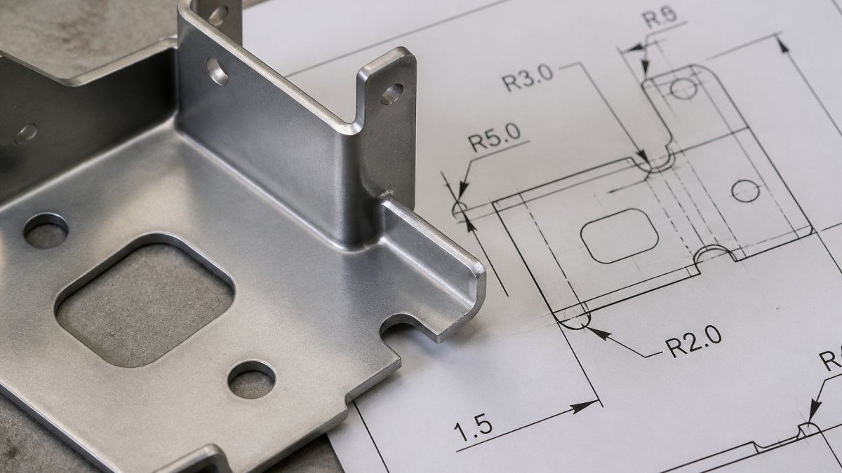
A flange is a formed edge created by bending material at a right angle (or close to it).
Flange length affects forming difficulty. Short flanges (under 5mm) are relatively easy; flanges longer than 20mm demand careful design and often progressive tooling.
Minimum flange length is usually 2-3 times material thickness. A 1.5mm thick part can have a 3mm flange, but 5mm is safer.
Corner reliefs prevent cracking at inside corners where two flanges meet. Without relief, material has nowhere to go as it's forced into a sharp corner.
Tabs are small projections used for alignment, fastening, or location. They're weaker than flanges because less material supports them.
Disc Springs EN 16983 DIN 2093 6mm to 28mm O/D →
Design guidelines for flanges, tabs, and reliefs:
- Minimum flange length: 5mm (or 3× material thickness)
- Maximum flange length without progressive tooling: 20mm
- Minimum bend radius at flange corners: equal to material thickness
- Corner relief depth: minimum 1.5× material thickness
- Corner relief radius: match or exceed bend radius
- Tab width: minimum 6mm, preferably 8-10mm
- Tab corner radius: minimum 1mm
Set Realistic Pressed Metal Tolerances and Dimensioning
Tolerances are where design intent meets manufacturing reality. Too tight and every part fails inspection; too loose and assembly becomes a nightmare.
Pressed parts typically hold ±0.5mm tolerances on formed features without special effort. Tighter tolerances (±0.25mm) require secondary operations, tighter tooling control, or both, each level of tightness adds cost and cycle time.
Hole positions are the most critical tolerance. A hole 0.5mm off-centre might be invisible but makes fastener assembly impossible. Hole position tolerance is typically ±0.3mm for production parts, ±0.2mm for tight applications.
Flange dimensions and angles are harder to hold tight than you'd expect. A 90-degree flange often comes out at 89.5 or 90.5 degrees depending on springback. If your design requires exactly 90 degrees, you need secondary operations to correct it.
Datum selection is critical for dimensioning.
Tolerance guidelines for pressed components:
- General dimensions: ±0.5mm without secondary operations
- Hole positions: ±0.3mm for standard, ±0.2mm for tight tolerances
- Flange angles: ±1 degree without secondary operations
- Surface flatness: ±0.5mm over 100mm span
- Edge straightness: ±0.3mm over 50mm span
Document tolerances clearly. Use geometric dimensioning and tolerancing (GD&T) where appropriate. Ambiguous tolerances lead to disputes and rework.
Plan for Press-Specific Tooling and Die Design
This is where most designs disconnect from reality. A design that looks perfect in CAD can be impossible to tool. Tooling constraints directly influence what's actually manufacturable.
Progressive die design is the standard for high-volume pressed components.
The challenge: each station must work with material in its current state. A bend in station 3 works differently on pre-formed material than on flat stock. Dies must account for this.
Transfer press tooling is used when progressive dies won't work, when features are too complex or stations too far apart. Transfer presses move material between separate dies using mechanical arms.
Tooling cost scales dramatically with design complexity. A simple flat pattern with holes might cost £3,000 to £5,000. Add a deep flange and you're at £8,000 to £12,000.
Key tooling considerations:
- Minimise the number of bends (each bend requires a station or separate die)
- Avoid features that require manual secondary operations
- Design for progressive die flow whenever possible
- Provide adequate clearance for die components
- Avoid sharp internal corners that require complex punch geometry
- Plan for scrap strip width and nesting efficiency
Die wear is another hidden cost. Sharp punch corners wear quickly. Rounded corners last longer but affect part geometry.
Validate Design and Prototype Before Full Production
Many expensive failures happen because designs were never tested before committing to production tooling. A prototype catches issues that calculations miss.
The validation process should follow this sequence: design review, prototype build, dimensional inspection, functional testing, then production.
Design review is the first gate. Have the design reviewed by someone with pressing experience, they'll spot issues you missed.
Prototype build reveals what's actually possible.
Dimensional inspection confirms tolerances are achievable. Measure every critical dimension against the design specification. If tolerances are unachievable, adjust the design or the manufacturing process.
Functional testing validates that the part works in its intended application: does it fit the assembly, withstand design loads, pass durability testing?
Validation checklist before production:
- Design review completed with manufacturing input
- Prototype built and dimensionally inspected
- All critical tolerances verified achievable
- Functional testing completed successfully
- Die design reviewed for manufacturability
- Scrap rate and cycle time estimated
- Quality control plan documented
- First article inspection criteria defined
Getting pressed metal component design right means balancing cost, manufacturability, performance, and timeline. The designs that succeed are those where manufacturing input happens early, not late.
When you're ready to move from design to production, SpringXpert can help validate your approach.
| Design Element | Tolerance Range | When to Specify Tighter |
|---|---|---|
| General dimensions | ±0.5mm | Assembly fit-up critical |
| Hole positions | ±0.3mm | Fastener alignment required |
| Flange angles | ±1 degree | Structural load-bearing |
| Edge straightness | ±0.3mm | Aesthetic or fit surfaces |
| Surface flatness | ±0.5mm per 100mm | Sealing or contact surfaces |
Pro Tip
Start your prototype with the loosest tolerances your application allows. Tighten only the dimensions that actually matter for fit, function, or appearance. Each tighter tolerance adds cost and risk. Many designs over-specify simply out of habit.
Watch Out
Never assume a design is manufacturable without manufacturing input. "It looks reasonable in CAD" is not a manufacturing approval. A design that violates bend radius rules or flange length minimums will fail in the press, wasting tooling investment and delaying production.
Frequently Asked Questions
What are the most common design mistakes that lead to pressed metal component failures?
The most frequent issues include insufficient bend radius (causing cracking), holes or slots placed too close to bends (weakening the part), inadequate flange length (leading to deformation), and unrealistic tolerances that exceed press capability. Springback compensation is often overlooked, causing dimensional drift in production. Designers sometimes ignore material grain direction, which affects formability. Poor relief design at corners creates stress concentration points. Early design validation through prototype testing catches these problems before tooling investment.
How does sheet metal bend radius affect pressed component design and material selection?
Bend radius must be at least 1 to 1.5 times the material thickness for most metals; softer materials like aluminium tolerate tighter radii, while harder steels require larger radii to prevent cracking. Thicker material demands proportionally larger bend radii. The radius affects springback (how much the metal rebounds after forming), which varies by alloy and temper. Insufficient radius concentrates stress, causing surface cracking and premature failure in service. Specifying proper bend radius in your drawing prevents die redesign and scrap. SpringXpert's technical team can advise on material-specific bend requirements during design review.
What tolerances should I specify for a pressed metal component, and how do they affect tooling cost?
Realistic tolerances for pressed metal are typically ±0.5 mm to ±1.0 mm on formed features, depending on material thickness and part complexity. Tighter tolerances (±0.25 mm) require precision tooling, secondary finishing, and inspection, significantly increasing cost. Looser tolerances reduce tool wear and scrap, lowering per-unit cost. Datum references and GD&T (geometric dimensioning and tolerancing) clarify which surfaces matter most. Specify only the tolerances your application genuinely requires. High-volume production justifies tighter control; prototypes and small batches should use relaxed tolerances to reduce tooling cost and lead time.
How can I design pressed metal components to minimise tooling cost and production scrap?
Simplify geometry: avoid unnecessary features, tight radii, and sharp corners that require additional tooling steps. Design for progressive-die or transfer-press operation if volume justifies it; these reduce scrap and labour cost per part. Specify material thickness that balances strength with formability, thinner material forms more easily but may not meet strength requirements. Plan hole and slot positions to avoid tool access conflicts. Use standard bend radii and flange dimensions where possible. Prototype with the intended production method to validate design before committing to tooling. SpringXpert's design consultation can identify cost-reduction opportunities specific to your production volume and application.