

Custom Torsion Spring Tolerance Requirements: Ultimate Guide
Table of Contents
- Why Torsion Spring Tolerance Requirements Decide Fit and Function
- Torsion Spring Dimensional Tolerances: Wire, Diameter, and Legs
- Torsion Spring Torque Tolerance: Controlling Load and Deflection
- Torsion Spring Measurement: Inspection Methods and Acceptance Criteria
- Torsion Spring Drawing Specifications: A Dimension-by-Dimension Checklist
- How Tolerance Stack-Up Affects Fit and Installed Performance
- Choosing Tolerance by Application Criticality and Manufacturing Capability
- Frequently Asked Questions
Last Updated: October 18, 2026
Why Torsion Spring Tolerance Requirements Decide Fit and Function
Custom torsion spring tolerance requirements are the agreed limits on every dimension and torque value a bespoke spring must meet, and they decide whether a component drops into an assembly or fights it.
Tighter tolerances buy predictability and cost money; looser tolerances buy economy and export risk into your assembly. Getting that trade-off right starts with understanding what each callout controls.
Key Takeaway
Tolerance is not a quality badge. It is a commercial decision about how much variation your assembly can absorb before something jams, rattles or fatigues early.
Torsion Spring Dimensional Tolerances: Wire, Diameter, and Legs
Dimensional tolerance is the allowable variation on a physical feature, and it is where most specification arguments begin. Four families carry almost all the risk: wire, coil diameter, leg geometry and free position.
Wire Diameter and Coil Diameter Tolerances
Wire diameter governs spring rate and stress, so it deserves the tightest realistic band you can afford; the spring maker cannot improve on the graded wire it receives. Inside diameter matters most when the spring winds onto a mandrel or shaft. A common mistake is specifying inside diameter alone and assuming outside diameter will look after itself.
Leg Length, Leg Angle, and Leg Position Tolerances
Legs are the working end of a torsion spring and the hardest feature to hold. Leg length, leg angle and leg position all interact with free position, so tolerancing them in isolation invites stack-up problems. Angular leg tolerances are expressed in degrees from a datum, and that datum must be defined on the drawing.
| Feature | What It Controls | Typical Risk If Loose |
|---|---|---|
| Wire diameter | Spring rate, stress | Load scatter |
| Inside diameter | Shaft fit | Binding or rattle |
| Outside diameter | Housing clearance | Interference |
| Leg length | Engagement point | Poor seating |
| Leg angle | Installed preload | Wrong working angle |
| Free position | Rest geometry | Assembly misalignment |
Torsion Spring Torque Tolerance: Controlling Load and Deflection
Torque tolerance defines the permitted spread in torque at a stated working angle and most directly predicts field behaviour. Because torque depends on wire diameter, coil diameter, active coils, material properties and heat treatment, a torque band is really a statement about how well those inputs are controlled together.
Torque tolerance is a derived tolerance: you cannot inspect it into existence at the end of the line. When a customer asks for a tight torque band, we look first at whether the wire specification supports it.
How Torque Tolerance Is Derived
For a torsion spring loaded within its elastic range, torque at a given angular deflection follows the relationship:
T = (E · d⁴ · θ) / (3,670 · D · N)
where T is torque in newton-millimetres, E is Young's modulus in N/mm² (about 206,000 for music wire, 193,000 for stainless spring steels), d is wire diameter in millimetres, θ is angular deflection in degrees, D is mean coil diameter in millimetres and N is the number of active coils.
Because d enters the equation to the fourth power, wire diameter dominates torque: a 2% shift in wire diameter moves torque by roughly 8%, versus roughly 2% for a 2% shift in mean coil diameter.
Practical Torque Tolerance Bands
There is no single statutory torque tolerance for custom torsion springs in the UK; the band is a commercial agreement constrained by what the process can hold. The bands below are commonly achievable and a sensible RFQ starting point:
| Torque band at stated working angle | Typical application | Manufacturing implication |
|---|---|---|
| ±5% | Safety-critical actuators, precision instruments | Requires controlled wire grade, in-process torque checks and usually 100% functional test |
| ±10% | General industrial mechanisms, robotics joints | Standard bespoke production with lot sampling |
| ±15% | Non-critical hinges, return springs, covers | Economic band; wire grade alone may govern |
| ±20% or wider | Cosmetic or low-cycle applications | Only where load scatter does not affect function |
These are indicative, not universal. A spring with a very low active-coil count or a short leg will struggle to hold ±5%, because small forming variations translate into large angular errors.
The Working Angle Must Be Stated
Torque tolerance is meaningless without the angle at which it is measured. Two conventions dominate:
- Torque at a stated working angle, for example, "0.85 N·m ±10% at 90° from free position." This is the clearest callout and the one we recommend.
- Torque at a stated deflection from free, for example, "0.85 N·m ±10% at 90° deflection." Acceptable, but it relies on the free position being toleranced too, otherwise the measurement angle drifts.
A third, weaker convention is "torque at installed position," which pushes the measurement definition into the assembly drawing and creates ambiguity at goods-in inspection. Avoid it unless the installed position is a toleranced, repeatable datum.
Watch Out
Specifying a torque tolerance without stating the working angle it applies at is the single most common drawing error we see. The number is meaningless until the measurement angle is fixed, and if the free position is not toleranced, even a stated working angle can drift.
Torque Tolerance Versus Spring Rate Tolerance
Torque tolerance and spring rate tolerance are related but not interchangeable. Torque tolerance controls load at one point; rate tolerance controls how load changes between two points.
Where load progression matters, specify both: torque at the working angle with a band, and rate with a separate band (commonly ±10% to ±15%). If only one can be held tightly, hold torque at the working angle, because that is the point the assembly actually feels.
What Drives Torque Out of Band
The usual culprits, in rough order of impact:
- Wire diameter drift, the fourth-power relationship means small incoming wire variation dominates. Specify the wire band explicitly and ask for the incoming wire certificate.
- Heat treatment variation, stress relieving and hardening cycles shift Young's modulus and residual stress; mixed batches in one furnace load widen torque scatter.
- Active coil count, forming variation changes the effective number of active coils, moving rate and torque together.
- Leg geometry, leg angle and length errors change the effective moment arm, so torque can read out of band even when the coil is correct.
- Measurement setup, load cell calibration, fixture stiffness and reading angle all contribute. A torque result is only as good as the fixture that produced it.
Inspection Angle and Acceptance
State the inspection angle on the drawing, not in a separate quality plan.
Where a customer needs a tighter torque band than the process can hold, the honest options are: tighten the wire specification, add a 100% functional torque test, or redesign the assembly to absorb more scatter. Promising a band the process cannot hold is not one of them.
Torsion Spring Measurement: Inspection Methods and Acceptance Criteria
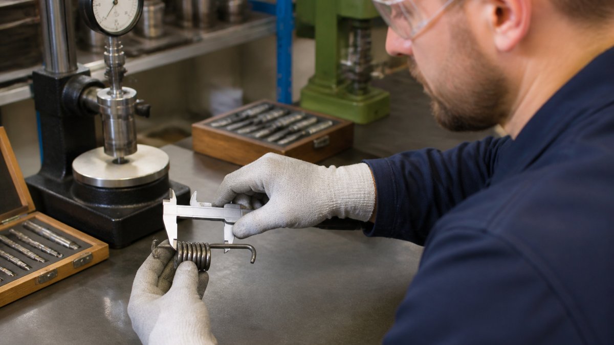
Acceptance criteria should be written on the drawing itself. Where quality systems are audited, the ISO 9001 quality management standard gives the framework most buyers expect a spring supplier to work within.
Torsion Spring Drawing Specifications: A Dimension-by-Dimension Checklist
Torsion spring drawing specifications are the written contract between designer and maker. The gap most drawings leave is not missing dimensions but missing tolerance callouts, datums and acceptance criteria. The checklist below is organised dimension by dimension so each line carries a tolerance band and a measurement basis, not just a nominal value.
Units, Datums and Drawing Conventions
Before any dimension, fix the conventions:
- Units, state millimetres and newtons (or newton-millimetres) explicitly; mixed metric and imperial drawings cause recurring quoting errors.
- Projection, first-angle or third-angle, stated in the title block. UK practice is normally first-angle, but the key is that it is stated.
- Datums, define a primary datum (usually the coil axis) and a secondary datum (usually the free leg or a leg plane). Every angular callout should reference a datum, not a neighbouring feature.
Dimension-by-Dimension Tolerance Reference
The table below consolidates the tolerance bands custom torsion spring drawings typically carry. They are indicative of what bespoke production can hold, not a statutory schedule; the correct band depends on wire size, coil count and application criticality.
| Feature | What to call out | Typical bespoke band | Measurement basis |
|---|---|---|---|
| Wire diameter | Nominal plus band | ±0.02 mm for wire up to 1.0 mm; ±0.03 mm for 1.0-3.0 mm; ±0.05 mm above 3.0 mm | Micrometer, three readings per lot |
| Inside diameter | Nominal plus band, referenced to shaft | ±0.15 mm typical; ±0.10 mm where the spring winds onto a mandrel | Pin gauge or internal micrometer |
| Outside diameter | Nominal plus band, referenced to housing | ±0.20 mm typical; derived from inside diameter plus twice wire diameter | Calliper or ring gauge |
| Free length | Nominal plus band | ±0.5 mm for short springs; ±1.0 mm for long coils | Height gauge on a flat surface |
| Number of coils | Total and active | Total ±0.25 coil; active as designed | Visual count against drawing |
| Leg length | Nominal plus band, from datum | ±0.5 mm typical; ±0.25 mm where the leg engages a slot | Calliper or vision system |
| Leg angle | Degrees from datum | ±2° typical; ±1° where preload is critical | Angle gauge or vision system |
| Leg position | Angular location of leg relative to datum | ±3° typical | Vision system or functional gauge |
| Free position | Angular relationship of legs at rest | ±3° typical | Functional gauge |
| Working angle | Stated deflection from free | As designed, with a stated measurement tolerance of ±0.5° | Torque tester with angle encoder |
| Torque at working angle | Value plus band | ±10% typical; ±5% for critical work | Calibrated torque tester |
| Spring rate | Value plus band where load progression matters | ±10% to ±15% | Two-point torque measurement |
| Winding direction | Right-hand or left-hand | Attribute, no band | Visual |
| Direction of operation | Loading direction relative to winding | Attribute, no band | Visual and functional |
| Material grade | Grade and condition | Attribute, with certificate | Mill certificate |
| Surface finish | Coating or passivation requirement | Attribute, with standard reference | Visual and coating thickness gauge |
Two cautions. First, the bands are not additive, a spring with tight wire and inside diameter bands will still show wider torque scatter than either alone suggests, because torque depends on both.
Inspection, Sampling and Acceptance Criteria
The drawing should carry the acceptance basis, not a separate quality plan that arrives after the order. A workable callout reads:
- Inspection method, name the gauge or tester for each toleranced feature (micrometer, pin gauge, torque tester with angle encoder, vision system).
- Sampling plan, reference BS 6001-1 (ISO 2859-1) with inspection level and AQL, or state 100% inspection for safety-critical features.
- Acceptance criterion, pass/fail against the drawing band, with measurement uncertainty stated so a reading on the limit is not ambiguous.
Where quality systems are audited, the ISO 9001 quality management standard gives the framework most buyers expect a spring supplier to work within, and BS 8888 covers the drawing conventions themselves.
RFQ Checklist
Use this list before issuing an RFQ. Each line should be answerable from the drawing alone:
- Units and projection stated in the title block
- Primary and secondary datums defined
- Wire diameter with tolerance band and material grade with condition
Complete that list and you have a specification a manufacturer can quote against without guessing, and a goods-in inspection that will not end in a dispute about what the drawing meant.
How Tolerance Stack-Up Affects Fit and Installed Performance
Tolerance stack-up is the accumulation of individual allowable variations into a combined installed result, and it is why a set of "reasonable" tolerances can still produce an assembly that will not close.
The practical fix is to tolerance the assembly-critical dimension last. Decide what installed performance you need, then work backwards to the individual bands that deliver it. Where a stack-up is genuinely tight, ask for a statistical rather than arithmetic treatment.
Winding Direction and Direction of Operation
Winding direction describes how the coil is formed; direction of operation describes how the spring is loaded in service. They must be stated together, because a spring wound one way and operated the other will unwrap rather than load, and no tolerance band will save it.
Choosing Tolerance by Application Criticality and Manufacturing Capability
Tolerance selection should follow application criticality first and manufacturing capability second, never the reverse. A safety-critical subsea actuator and a cosmetic hinge do not deserve the same bands.
Ask three questions: what happens if this feature drifts to its limit, can the process hold the band repeatably, and what does inspection cost at that band? Where the answers point to a tight tolerance, confirm the manufacturer's capability before you commit.
As documented in the BSI guide to tolerancing and dimensioning standards, unambiguous drawing conventions are the foundation of any supplier agreement. For material behaviour under repeated load, the University of Cambridge's materials teaching resources offer a useful grounding in fatigue and elastic behaviour.
Frequently Asked Questions
What tolerances should I specify for a custom torsion spring?
Specify tolerances based on the spring's role in the assembly. For wire diameter, a standard tolerance is ±0.05 mm; outside diameter ±0.25 mm; leg length ±0.5 mm; leg angle ±2°; and torque ±10% of the working load. Tighten these only where the application demands it, because tighter tolerances raise cost and lead time. Always state units and reference standards on the drawing, and confirm the manufacturer's achievable range before finalising.
How are torsion spring tolerances measured?
Torsion spring measurement uses calibrated instruments: micrometers for wire diameter, callipers or pin gauges for coil and inside diameters, a protractor or vision system for leg angle, and a torque tester for load at a given deflection. Inspection should follow a documented plan with sampling per production lot. For critical springs, request first-article inspection reports and material traceability. Environmental conditions such as temperature and humidity should be controlled during measurement to avoid false rejections.
Which dimensions are critical when specifying a torsion spring?
The critical dimensions are wire diameter, outside and inside diameter, leg length, leg angle, leg position, free position, working angle, and winding direction. Torque at the working angle is equally important. Missing any of these on the drawing invites assumptions and rework. For assembly-critical springs, also define maximum angular deflection and expected cycle life so the supplier can select wire material and heat treatment that meet the tolerance band over time.
How do manufacturing tolerances affect torsion spring performance?
Tolerances affect spring rate, load at the working angle, and fatigue life. A wire diameter variation of just 0.02 mm can shift torque by several percent. Leg angle tolerance changes the installed preload, while coil diameter tolerance influences fit on the mandrel. Stack-up of several tolerances can push the spring outside its intended working range, causing premature failure or assembly rejection. Define tolerances that reflect the application's sensitivity, not just default shop standards.
Can torsion spring tolerances be customised?
Yes. Custom torsion spring tolerance requirements can be tailored to your assembly, but tighter tolerances increase cost and may extend lead time. Discuss your functional needs with the manufacturer early. For example, if a leg angle of ±1° is essential, the supplier may need to adjust forming and inspection methods. Provide a drawing with clear critical dimensions and ask for a capability study or sample inspection report to confirm the tolerance can be held consistently.
How should I specify torque and angular deflection for a torsion spring?
State the required torque at a specific angular deflection (e.g., 2.5 N·m at 90°). Include the working angle range and maximum deflection. Torque tolerance is typically ±10% for standard springs but can be tightened to ±5% for critical applications. Also note the direction of operation (clockwise or counterclockwise) and whether the spring will be cycled. Providing load-deflection data helps the manufacturer choose wire diameter, coil count, and material to meet the torque tolerance.
What information should a torsion spring drawing include?
A complete torsion spring drawing includes: wire diameter, outside and inside diameter, free length, number of coils, leg length, leg angle, leg position, free position, working angle, winding direction, material specification, surface finish, torque at specified angles, and tolerance for each dimension. Add notes on heat treatment, inspection requirements, and traceability. Reference relevant standards (e.g., BS or ISO) and include a title block with revision control. This reduces back-and-forth and ensures the finished spring meets the design intent.
How do I choose a suitable tolerance for a torsion spring application?
Start with the assembly's functional requirements: how much variation in torque or position can the system tolerate without affecting performance? Then match tolerances to manufacturing capability. For non-critical applications, standard tolerances keep costs down. For critical assemblies, tighten only the dimensions that matter and request capability data. Consider the full tolerance stack-up across mating parts. A supplier with ISO 9001 certification and experience in your sector can advise on realistic tolerances that balance cost and reliability.
Tolerance decisions made late are expensive. If your assembly depends on a bespoke torsion spring holding a tight torque band, leg angle and fit, SpringXpert can help: over 20,000 standard products, bespoke engineering backed by ISO 9001 certification, and more than 20 years of production experience behind every quote. Send us your drawing and working angle, and we will come back with a tolerance proposal that your assembly can actually live with.